Heat exchange core with flow guide switching section, heat exchanger and machining method

A technology of heat exchange core and transition section, which is applied in the field of heat exchange, can solve the problems of high cost and many processes, and achieve the effects of improving compressive strength, reducing welding processes, and ensuring processing accuracy

Pending Publication Date: 2022-01-07
陕西益信伟创智能科技有限公司
View PDF0 Cites 1 Cited by
  • Summary
  • Abstract
  • Description
  • Claims
  • Application Information

AI Technical Summary

Problems solved by technology

[0004] Most of the diversion optimizations for heat exchanger flow distribution are added or optimized for the inside of the liquid header, liquid collection chamber or head structure, but they are all for larger-sized heat exchanger structures, and their collection The liquid pipe is relatively large, and its shape is close to a semi-cylindrical.

Method used


Image

  • Heat exchange core with flow guide switching section, heat exchanger and machining method
  • Heat exchange core with flow guide switching section, heat exchanger and machining method
  • Heat exchange core with flow guide switching section, heat exchanger and machining method

Examples


Embodiment 1

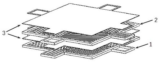
[0060] A heat exchange core with a diversion transfer section, such as Figure 2a-2b , including a plurality of stacked heat exchange units, each heat exchange unit includes a first heat exchange plate 1, a second heat exchange plate 2 and a separator 3;

[0061] The first heat exchange plate 1 is provided with an edge seal 12, and the fins 8 are arranged inside the edge seal 12; the first heat exchange plate 1 is provided with a first liquid collecting pipe 9 opposite to it and a second liquid collector 9 opposite to it. Liquid collecting pipe 10, the contour of the first liquid collecting pipe 9 and the second liquid collecting pipe 10 is the same;

[0062] Wherein, the fins 8 extend into the first liquid collection pipe 9, and each flow channel formed by the fins 8 on the first heat exchange plate 1 can communicate with the first liquid collection pipe 9, and the first liquid collection pipe The fins 8 in the tube 9 are in a through structure, and the second liquid collect...

Embodiment 2

[0068] Such as Figure 3a-3b As shown, the fins 8 are herringbone, and the fins 8 are arranged on one side of the first heat exchange plate 1 and the second heat exchange plate 2, and the fins 8 are all arranged on the first heat exchange plate 1 and the second heat exchange plate. The upper surface or the lower surface of the heat exchange plate 2; in some embodiments, the fins 8 are all arranged on the upper surfaces of the first heat exchange plate 1 and the second heat exchange plate 2, and the upper surface of the fin 8 and the edge sealing The upper surface of 12 is flush.

[0069] The fins 8 in the first liquid collection pipe 9 extending to the fluid inlet extend to connect with the edge sealing 12, cutting and guiding the fluid in the first liquid collection pipe 9 to the flow channel inside the heat exchange plate to realize liquid collection Flow distribution in the tube; the fins 8 inside the heat exchange plate are interrupted to ensure that each flow channel for...

Embodiment 3

[0086] Such as Figures 9a-9g As shown, the inlet and outlet are arranged in a diagonal line, and the fins 8 are parallel straight or zigzag rib columns; sawtooth fins, corrugated fins, and rib columns can also be used; extend to the first episode The fins 8 in the liquid pipe 9 are closed and connected, and the fluid in the first liquid collection pipe 9 is cut and guided to the flow channel inside the heat exchange plate through the fins 8 with an inclination angle β; the fins 8 with an inclination angle β are connected with The position where the straight fins 8 meet is provided with rib columns; the inclination angle β is adjusted according to the structure of the heat exchange plate and the position of the inlet and outlet, but it is not more than 90° from the mainstream direction of the fluid, and the array spacing of the rib columns is 1 to 1.5 times the pitch of the fins 8, and the fins 8 are staggered in the middle of the heat exchange plates.

[0087] The number of ...


PUM

PropertyMeasurementUnit
Thicknessaaaaaaaaaa
Roughnessaaaaaaaaaa

Abstract

The invention discloses a heat exchange core with a flow guide switching section, a heat exchanger and a machining method. The heat exchange core comprises a plurality of stacked heat exchange units, and each heat exchange unit comprises a first heat exchange plate, a second heat exchange plate and a partition plate; sealing edges are arranged on the peripheries of the first heat exchange plates, and fins are arranged in the sealing edges; first liquid collecting pipes which are opposite in position and second liquid collecting pipes which are opposite in position are arranged on the peripheries of the first heat exchange plates; the second heat exchange plates and the first heat exchange plates are the same in structure, the positions of the second heat exchange plates and the first heat exchange plates rotate horizontally, so that flow channels of the first heat exchange plates and the second heat exchange plates are arranged in a cross flow mode, and the corresponding liquid collecting pipes are aligned; and the partition plates are arranged on the sides, provided with the fins, of the first heat exchange plates and the second heat exchange plates. The liquid collecting pipes at the inlet and the outlet and the heat exchange plates are integrally machined, the pipelines are externally connected with the heat exchange core through the cover plate, the influence of welding high temperature on the precision structure of core plates is avoided, and meanwhile fluid flows and is distributed more evenly at the inlet of the core.

Description

technical field [0001] The invention belongs to the technical field of heat exchange, and relates to a heat exchange core body with a flow guiding transition section, a heat exchanger and a processing method. Background technique [0002] Heat exchangers play an indispensable role in many industrial production fields today. Through their structural characteristics, heat exchangers enable heat exchange between hot fluid and cold fluid to achieve energy recovery and utilization. The usual plate or plate-fin heat exchanger is composed of partitions, heat exchange channels, frame seals and other structures, and is produced and processed by stacking, assembling and welding. For the laminated heat exchanger with tiny channels, inlets and outlets are set up for different working fluids in the small plate space, and the liquid collection device is welded outside the core. After being collected by the liquid collection device, it flows into or discharges from the heat exchanger core....

Claims


Application Information

Patent Timeline
IPC IPC(8): F28D9/00F28F3/04F28F3/08F28F9/22F28F9/24
CPCF28D9/0068F28F3/046F28F3/08F28F9/24F28F9/22F28F2009/222
Inventor 侯雨田王俊伟姜会庆杨家旺
Owner 陕西益信伟创智能科技有限公司
Why Eureka
Try Eureka