Flow monitoring device for air energy heat pump

An air-energy heat pump and flow monitoring technology, which is applied in measuring devices, electromagnetic flowmeters to detect fluid flow, volume/mass flow generated by electromagnetic effects, etc., can solve the problems of unable to monitor and calculate pressure and flow velocity in real time

Active Publication Date: 2022-01-07
山东华盛环境工程有限公司
View PDF5 Cites 0 Cited by
  • Summary
  • Abstract
  • Description
  • Claims
  • Application Information

AI Technical Summary

Problems solved by technology

[0003] In order to make reasonable use of air energy, it is necessary to monitor and control the flow rate during daily use of air source heat pumps; especially when the heat load fluctuates, it is necessary to monitor the flow rate of the heat source to avoid heat loss; the existing flow rate The monitoring device can only monitor the flow change of the fluid in the pipe, but it cannot monitor and calculate the pressure and flow velocity in the pipe in real time during the heating peak. A flow monitoring device for air energy heat pump

Method used


Image

  • Flow monitoring device for air energy heat pump
  • Flow monitoring device for air energy heat pump
  • Flow monitoring device for air energy heat pump

Examples


Embodiment 1

[0034] Embodiment 1: This embodiment is the principle of utilizing the flow monitoring device in the present invention to monitor and measure the pressure in the pipe:

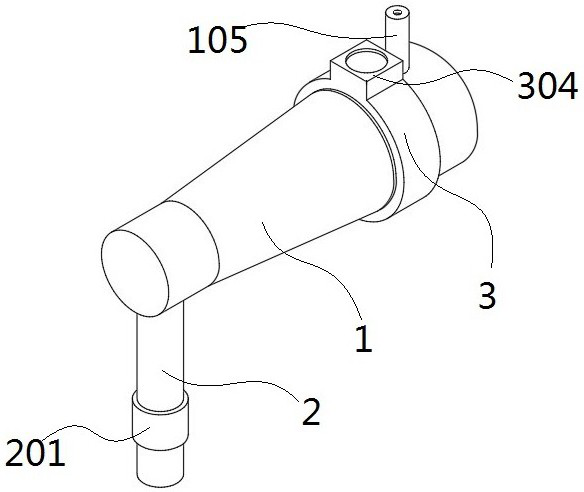
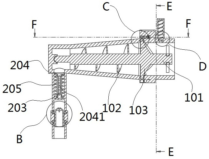
[0035] When the above-mentioned monitoring is required, when the heat pump is stopped, first adjust the pressure regulating sleeve 201 to make the pressure in the pipe the same as the atmospheric pressure, then turn on the heat pump compressor, and the air flow will impact the conveying plate 103 under the pressurized state to make it rotate, and then gradually The level is sent to the pressure regulating pipe 2, and the one-way valve pipe 204 is opened at the same time, and in the case of full communication, the pressure indicating pipe 105 can directly display the current pressure in the pipe.

Embodiment 2

[0036] Embodiment 2: This embodiment is the principle of utilizing the flow monitoring device in the present invention to monitor and calculate the fluid velocity in the pipe:

[0037] When the above-mentioned monitoring is required, the flow rate under the current pressure environment can be obtained by dividing the flow rate in the pipe when the conveying disk 103 rotates once by the time interval by the method of calculating the flow rate.


PUM


Abstract

The invention discloses a flow monitoring device for an air energy heat pump, and relates to the technical field of energy-saving heat pumps. The flow monitoring device comprises a conveying connecting pipe, a pressure regulating pipe and an electromagnetic monitoring sleeve, wherein a conveying screw is arranged in the conveying connecting pipe, a spiral keel and a conveying disc are installed on the peripheral side face of the conveying screw, and a permanent magnet bolt is arranged on the surface of the conveying disc, and is matched with a magnetic guide bolt in the electromagnetic monitoring sleeve, the conveying disc is arranged, air flow impacts a vortex plate on the surface of the conveying disc to enable the vortex plate to rotate, on one hand, the air flow can be conveyed to the next stage through an air hole and a spiral keel, and on the other hand, the rotating conveying disc drives the magnetic guide bolt to rotate, and magnetic force signals are converted into electric signals. A timing instrument is used for recording the circulating time of the fixed flux, the flow of fluid in the pipe can be monitored, and the flow speed of internal air flow can be monitored in real time; and then the flow monitoring device is matched with a subsequent pressure regulating pipe and a pressure indicating pipe to measure and calculate the pressure of fluid in the pipe, so that multiple monitoring work of flow, flow velocity and pressure in the heat pump pipe is realized.

Description

technical field [0001] The invention belongs to the technical field of energy-saving heat pumps, and in particular relates to a flow monitoring device for air energy heat pumps. Background technique [0002] Air energy heat pump is a low-grade thermal energy resource formed by using the solar energy and geothermal energy of the shallow air on the earth's surface. It adopts the principle of heat pump and realizes the transfer of low-level thermal energy to high-level thermal energy through a small amount of high-level electric energy input. It is also based on Therefore, in recent years, air energy heat pump technology has been widely used in the field of heating; [0003] In order to make reasonable use of air energy, it is necessary to monitor and control the flow rate during daily use of air source heat pumps; especially when the heat load fluctuates, it is necessary to monitor the flow rate of the heat source to avoid heat loss; the existing flow rate The monitoring devi...

Claims


Application Information

Patent Timeline
Patent Type & Authority Applications(China)
IPC IPC(8): G01F1/58G01D21/02
CPCG01F1/584G01D21/02
Inventor 高学亮王坤高圣洋崔峻通王娟高晓晖刘加增付平
Owner 山东华盛环境工程有限公司
Why Eureka
Try Eureka