
Electro-hydraulic integrated jumbolter control system and method

A technology of bolting rig and control system, which is applied to the automatic control system of drilling, installation of bolts, drilling equipment, etc. It can solve the problems of easy misoperation, low safety, and cumbersomeness, so as to avoid wear and reduce the number of oil pipes , The effect of eliminating potential safety hazards

Pending Publication Date: 2022-03-29
北京道思克能源设备有限公司
View PDF0 Cites 0 Cited by
  • Summary
  • Abstract
  • Description
  • Claims
  • Application Information

AI Technical Summary

Problems solved by technology

[0006] Aiming at the above-mentioned deficiencies in the prior art, an electro-hydraulic integrated rock bolt control system and method provided by the present invention solve the problem of bulky, cumbersome, low safety and prone to misoperation caused by many actuators of the rock bolt during operation. question

Method used


Image

  • Electro-hydraulic integrated jumbolter control system and method
  • Electro-hydraulic integrated jumbolter control system and method
  • Electro-hydraulic integrated jumbolter control system and method

Examples


Embodiment 1

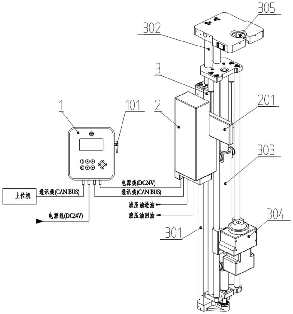
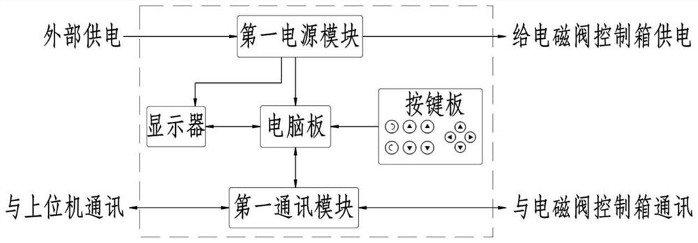
[0046] Such as figure 1 As shown, in one embodiment of the present invention, an electro-hydraulic integrated rock bolt control system includes a man-machine operation station 1, a solenoid valve control box 2 and a rock bolt 3 connected in sequence;

[0047] Wherein, the rock bolter 3 includes a main frame 301, a supporting mechanism hydraulic cylinder 302, a feeding mechanism hydraulic cylinder 303, a drilling cabin hydraulic motor 304, and a jaw mechanism 305; the bottom of the supporting mechanism hydraulic cylinder 302 is fixedly arranged on the The top of the main frame 301, the top of the supporting mechanism hydraulic cylinder 302 is movably connected with the fixed part of the jaw mechanism 305, and the rotating output end of the hydraulic motor 304 of the drill box is connected with the anchor rod of the rock bolt rig 3. The fixed connection end of the hydraulic motor 304 of the drill box is connected with the movable end of the hydraulic cylinder 303 of the feeding ...

Embodiment 2

[0062] This embodiment is directed at the implementation method of the electro-hydraulic control system for drilling and anchoring;

[0063] Such as Figure 4 As shown, in this embodiment, an electro-hydraulic control method for drilling and anchoring includes the following steps:

[0064] S1. Send the operation signal to the solenoid valve control box 2 through the man-machine operation station 1 according to the drilling demand;

[0065] S2. According to the operation signal received by the solenoid valve control box 2, the rock bolter 3 is controlled to drill.

[0066] The step S2 is specifically:

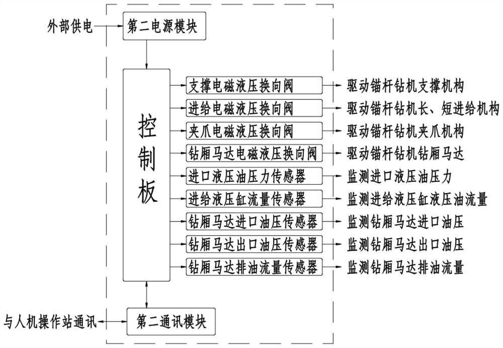
[0067] The control panel of the electromagnetic valve control box 2 receives the operation signal, drives the supporting electromagnetic hydraulic reversing valve to move, switches the oil inlet and oil return directions of the supporting mechanism hydraulic cylinder 302 of the rock bolter 3, and controls the extension of the supporting mechanism hydraulic cylinder 302. lengt...


PUM


Abstract

The invention discloses an electro-hydraulic integrated jumbolter control system and method. The system comprises a man-machine operation station, an electromagnetic valve control box and a jumbolter which are connected in sequence. The electromagnetic valve control box of the electro-hydraulic integrated jumbolter control system is directly installed on the jumbolter through the hydraulic valve plate, the number of oil pipes connected with a traditional manual reversing valve set and the jumbolter can be reduced, and abrasion to the oil pipes caused by dragging the oil pipes when all mechanisms of the jumbolter act is avoided; and potential safety hazards brought to miners and equipment due to disorder of the oil pipes are eliminated.

Description

technical field [0001] The invention belongs to the field of drilling and anchoring for underground roadways in coal mines, and in particular relates to an electro-hydraulic integrated bolting machine control system and method. Background technique [0002] The hydraulic actuators included in the coal mine bolter include: support, short feed, long feed, bolt gripper, drill box, front and rear tilting mechanism, left and right tilting mechanism. Each of its actuators needs to be realized by hydraulic cylinder expansion and contraction. Each hydraulic cylinder needs two oil pipes to be connected with the manual hydraulic reversing valve. [0003] At present, the problems existing in the use of rock bolters for coal mines are: [0004] 1. There are many actuators on the rock bolter, and there are many manual hydraulic reversing valves, which makes the operation cumbersome, cumbersome, and prone to misoperation. [0005] 2. There are as many as 20 hydraulic oil pipes connected...

Claims


Application Information

Patent Timeline
Patent Type & Authority Applications(China)
IPC IPC(8): E21B44/00E21B44/06E21D20/00
CPCE21B44/00E21B44/06E21D20/003
Inventor 贾伟耿海涛耿文行张涛
Owner 北京道思克能源设备有限公司
Learn More