
Dynamic optical signal processing method and device, equipment and storage medium

A technology for optical signals and processing methods, applied in the field of equipment, storage media, devices, and dynamic optical signal processing methods, can solve problems such as inability to accurately locate the center position of dynamic optical signals, improve positioning accuracy and measurement accuracy, and ensure The effect of accuracy

Pending Publication Date: 2022-01-07
ZYBIO INC
View PDF0 Cites 0 Cited by
  • Summary
  • Abstract
  • Description
  • Claims
  • Application Information

AI Technical Summary

Problems solved by technology

[0005] In view of this, the main purpose of the present invention is to provide a dynamic optical signal processing method, device, equipment and storage medium, aiming to solve the technical problem that the most central position of each cuvette dynamic optical signal cannot be accurately located

Method used


Image

  • Dynamic optical signal processing method and device, equipment and storage medium
  • Dynamic optical signal processing method and device, equipment and storage medium
  • Dynamic optical signal processing method and device, equipment and storage medium

Examples


no. 1 example

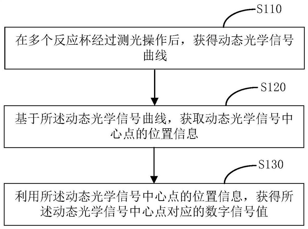
[0046] refer to figure 2 , figure 2 As the first embodiment of the dynamic optical signal processing method of the present application, the method includes the following steps:

[0047] Step S110: Obtain a dynamic optical signal curve after a plurality of cuvettes undergo a photometry operation;

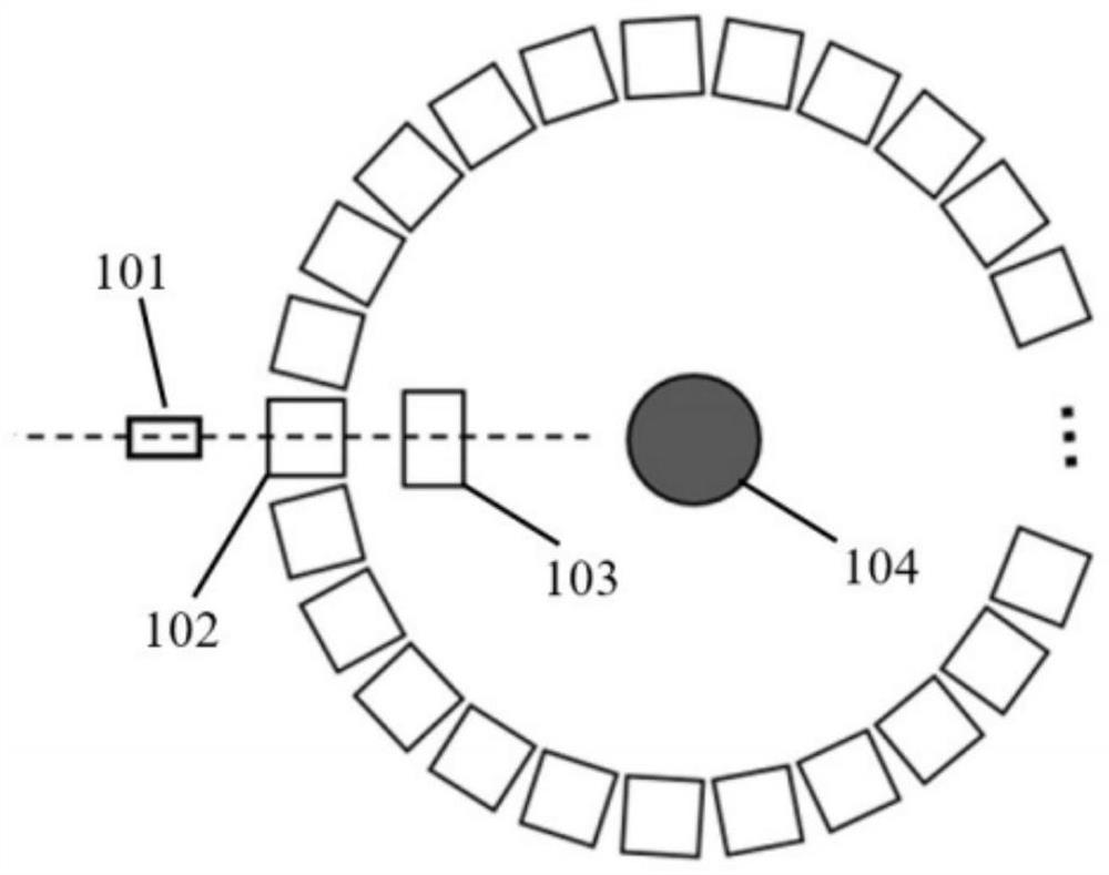
[0048] The automatic biochemical analyzer is a commonly used in vitro diagnostic analysis instrument. The spectrophotometer is its most important signal detection system. After the measurement light source irradiates the cuvette, it is received by the detector, and the optical signal is converted into a digital signal after photoelectric conversion processing. Value, the absorbance of the measured substance can be obtained by calculating the digital signal value, and finally the concentration or activity of the measured substance can be calculated according to the calibration or calibration coefficient of the instrument.

[0049] The acquisition of the light signal of the spectro...

no. 2 example

[0062] refer to Figure 5 , Figure 5 It is the second embodiment of the dynamic optical signal processing method of the present application, the method includes:

[0063] Step S210: Obtain a dynamic optical signal curve after a plurality of cuvettes undergo a photometry operation;

[0064] Specifically, the dynamic optical signal of the cuvette is obtained, and the curve is as follows Image 6 As shown, let the function of the curve be

[0065] the y n = f n (x) (1)

[0066] Where n represents the nth cuvette, x represents the serial number of the sampling point, and y represents the value of the digital signal.

[0067] Step S220: Based on the dynamic optical signal curve, obtain the maximum value and the minimum value of the dynamic optical signal.

[0068] Specifically, according to the dynamic optical signal curve, the maximum value and minimum value of the dynamic optical signal can be obtained directly or by mathematical methods such as derivation, which is not l...


PUM


Abstract

The invention discloses a dynamic optical signal processing method, device and equipment and a storage medium. The method comprises the following steps of: obtaining a dynamic optical signal curve after a plurality of reaction cups are subjected to light measurement operation; based on the dynamic optical signal curve, using a positioning algorithm to obtain position information of a dynamic optical signal central point; and obtaining a digital signal value corresponding to the dynamic optical signal central point by using the position information of the dynamic optical signal central point. Therefore, the technical problem that the centermost position of the dynamic optical signal of each reaction cup cannot be accurately positioned can be solved, and the positioning precision and measurement accuracy of the dynamic optical signal central point can be improved.

Description

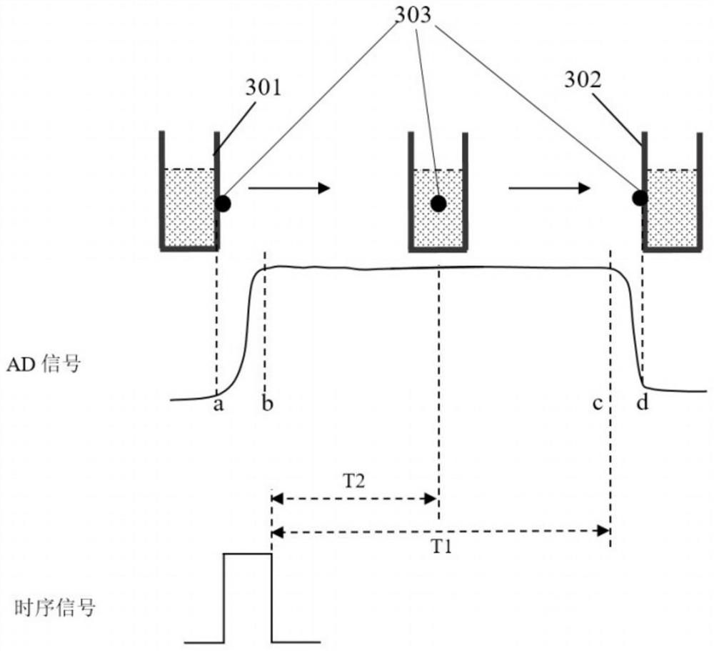
technical field [0001] The invention relates to the field of optical signal processing, in particular to a dynamic optical signal processing method, device, equipment and storage medium. Background technique [0002] At present, the commonly used method to determine the center point of dynamic optical signal is to use oscilloscope to measure and calibrate. Such as figure 1 As shown, the oscilloscope simultaneously measures the sampling timing control signal of the detector and the dynamic optical signal, adjusts the rising or falling edge of the timing signal to a fixed time interval T1 from the rising or falling edge of the dynamic optical signal curve, and then uses the timing signal The rising edge or falling edge of the oscilloscope is used as the reference, and the corresponding measured value on the dynamic optical signal curve is read after a certain time delay T2; and the shortcomings of the oscilloscope measurement and calibration method in the prior art are: [0...

Claims


Application Information

Patent Timeline
IPC IPC(8): G01N21/84G01N21/01
CPCG01N21/84G01N21/01G01N2021/0112
Inventor 张凤杰伍晋杰马德新
Owner ZYBIO INC
Learn More