
Debonding damage detection method, device and electronic equipment

A technology of damage detection and damage location, which is applied in measuring devices, measuring electrical variables, measuring resistance/reactance/impedance, etc., can solve the problem of low sensitivity of debonding damage detection

Active Publication Date: 2022-06-28
NORTHWESTERN POLYTECHNICAL UNIV
View PDF9 Cites 0 Cited by
  • Summary
  • Abstract
  • Description
  • Claims
  • Application Information

AI Technical Summary

Problems solved by technology

[0003] Based on this, the purpose of the embodiment of the present application is to provide a debonding damage detection method, device, and electronic equipment to solve the current problem of low detection sensitivity of debonding damage

Method used


Image

  • Debonding damage detection method, device and electronic equipment
  • Debonding damage detection method, device and electronic equipment
  • Debonding damage detection method, device and electronic equipment

Examples


Embodiment Construction

[0065] The technical solutions in the embodiments of the present application will be described below with reference to the accompanying drawings in the embodiments of the present application. For example, the flowchart and block diagrams in the Figures illustrate the architecture, functionality, and operation of possible implementations of systems, methods and computer program products according to various embodiments of the present invention. In this regard, each block in the flowchart or block diagrams may represent a module, segment, or portion of code that contains one or more functions for implementing the specified logical function(s) executable instructions. It should also be noted that, in some alternative implementations, the functions noted in the block may occur out of the order noted in the figures. For example, two blocks in succession may, in fact, be executed substantially concurrently, or the blocks may sometimes be executed in the reverse order, depending upo...


PUM

PropertyMeasurementUnit
diameteraaaaaaaaaa
diameteraaaaaaaaaa
thicknessaaaaaaaaaa

Abstract

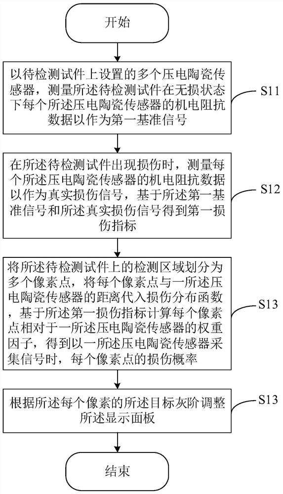
The present application provides a debonding damage detection method, device, and electronic equipment, which relate to the technical field of structure detection. The method includes: measuring the electromechanical impedance data of each piezoelectric ceramic sensor in a non-destructive state of the test piece to be tested as a first reference signal; when the test piece is damaged, the electromechanical impedance data of each piezoelectric ceramic sensor is measured as the real damage signal, and the first damage index is obtained based on the first reference signal and the real damage signal; The detection area is divided into multiple pixels, and the distance between each pixel and a piezoelectric ceramic sensor is substituted into the damage distribution function, and the weight factor of each pixel relative to a piezoelectric ceramic sensor is calculated based on the first damage index, so as to calculate The damage probability of each pixel point; and determine the disbonding damage position on the test piece to be tested. The method can solve the problem of low detection sensitivity of debonding damage at present.

Description

technical field [0001] The present application relates to the technical field of structure detection, and in particular, to a method, device and electronic device for detecting debonding damage. Background technique [0002] Bonded connections are widely used in engineering. Compared with traditional mechanical fastening, the stress transfer in bonded components is more uniform, and the structure of bonded components is better than that of mechanical fastening. Bonded connections are commonly used in composite materials, aircraft, spacecraft components, and other industrial components. Taking a solid rocket motor as an example, its casing, thermal insulation layer and propellant are all connected by bonding. Engine interface debonding, including shell insulation debonding, insulation lining debonding, and propellant debonding, is one of the most important failure modes of solid rocket motors and a weak link that limits engine life. With the increase of service time or stor...

Claims


Application Information

Patent Timeline
Patent Type & Authority Patents(China)
IPC IPC(8): G01N27/02G01R27/02
CPCG01N27/02G01R27/02
Inventor 杜飞樊浩东王光浩徐超
Owner NORTHWESTERN POLYTECHNICAL UNIV
Learn More