Painting system and method of painting
A coating and coating machine technology, which is applied to spraying devices, electrostatic spraying devices, liquid supply devices, etc., can solve problems such as high equipment costs, difficulty in reducing the number of coating system components, and increased man-hours for coating system manufacturing. Reduce the number of parts and achieve the effect of manufacturing man-hours
- Summary
- Abstract
- Description
- Claims
- Application Information
AI Technical Summary
Problems solved by technology
Method used
Image
Examples
no. 1 approach -
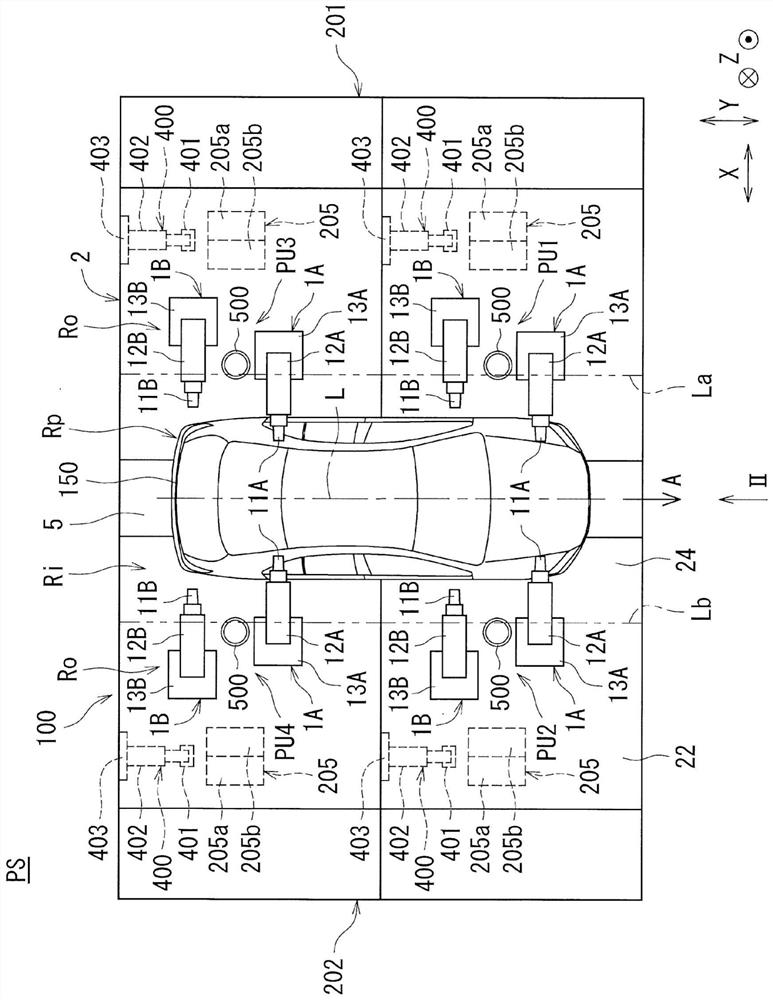
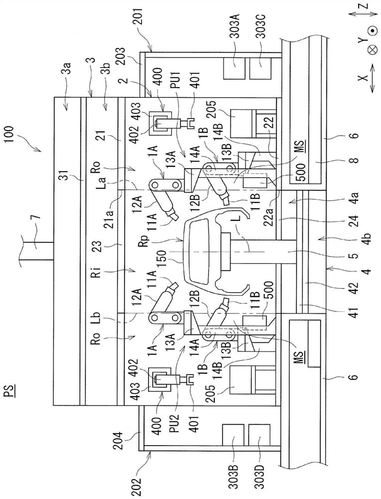
[0051] First, a first embodiment will be described. figure 1 It is a plan view which shows the painting system PS of this embodiment. also, figure 2 It is a front view showing the painting system PS of this embodiment (from figure 1 Figure observed in the direction of the arrow II). As shown in these figures, the painting system PS is equipped with the painting booth 100. A plurality of painting units PU1 , PU2 , PU3 , and PU4 are installed inside the painting booth 100 . In addition, auxiliary booths 201 and 202 are provided on both outer sides (both outer sides in the horizontal direction) of the paint booth 100 .
[0052] It should be noted that, in figure 1 with figure 2 Among them, the X direction is the width direction of the painting system PS, the Y direction is the length direction of the painting system PS (as the conveying direction of the vehicle body 150 of the object to be painted), and the Z direction is the height direction of the painting system PS (up...
no. 2 approach -
[0155] Next, a second embodiment will be described. In this embodiment, the arrangement|positioning form of each painting robot 1A, 1B of each painting unit PU1-PU4 differs from the arrangement|positioning form of the said 1st embodiment.
[0156] Figure 13 It schematically shows the movable range of the spray guns 11A, 11B realized by the robot arms 12A, 12B of the respective painting robots 1A, 1B in the first painting unit PU1 in this embodiment and the robot of the cassette conveying device 400. Top view of the movable area of the cartridge grip 401 realized by the arm 402 . as it should Figure 13 As shown, in each of the painting units PU1 (PU2 to PU4) in the painting system PS of this embodiment, as the arrangement positions of the first painting robot 1A and the second painting robot 1B, the first The painting robot 1A is arranged on the upstream side in the transport direction of the vehicle body 150 from the second painting robot 1B.
[0157] And, like the cas...
no. 3 approach -
[0160] Next, a third embodiment will be described. Also in this embodiment, the arrangement|positioning form of each painting robot 1A, 1B of each painting unit PU1-PU4 differs from the arrangement|positioning form of the said 1st embodiment.
[0161] Figure 14 It schematically shows the movable range of the spray guns 11A, 11B realized by the robot arms 12A, 12B of the respective painting robots 1A, 1B in the first painting unit PU1 in this embodiment and the robot of the cassette conveying device 400. Top view of the movable area of the cartridge grip 401 realized by the arm 402 . as it should Figure 14 As shown, in each of the painting units PU1 (PU2 to PU4) in the painting system PS of this embodiment, as the arrangement positions of the first painting robot 1A and the second painting robot 1B, the first The painting robot 1A is arranged on the downstream side of the second painting robot 1B in the transport direction of the vehicle body 150 , and the painting robot...
PUM
 Abstract
Description
Claims
Application Information
 - R&D
- Intellectual Property
- Life Sciences
- Materials
- Tech Scout
- Unparalleled Data Quality
- Higher Quality Content
- 60% Fewer Hallucinations
Browse by: Latest US Patents, China's latest patents, Technical Efficacy Thesaurus, Application Domain, Technology Topic, Popular Technical Reports.
© 2025 PatSnap. All rights reserved.Legal|Privacy policy|Modern Slavery Act Transparency Statement|Sitemap|About US| Contact US: help@patsnap.com


