
Pipe clamping device and pipe cutting machine

A clamping device and pipe technology, applied in the direction of tubular articles, applications, laser welding equipment, etc., can solve the problems affecting the rotation stability and cutting accuracy of the pipe, the lack of support and support for the pipe, and being easily affected by external forces. Avoid large jitter, save processing costs, and have the effect of stable rotation

Pending Publication Date: 2022-01-11
大展智能装备(广东)有限责任公司
View PDF0 Cites 0 Cited by
  • Summary
  • Abstract
  • Description
  • Claims
  • Application Information

AI Technical Summary

Problems solved by technology

[0003] When the current pipe cutting machine is processing a fixed-length pipe, in order to avoid damaging the appearance of the pipe, two clamping heads are often used to clamp and fix the inner holes at both ends of the pipe to achieve rotary cutting and drilling. However, because the pipe has a certain length, it is easily affected by external forces, and the pipe will vibrate during the rotation process, especially the middle position of the pipe lacks support and support, and the vibration is relatively large, which will affect the rotation stability and cutting of the pipe. Precision

Method used


Image

  • Pipe clamping device and pipe cutting machine
  • Pipe clamping device and pipe cutting machine
  • Pipe clamping device and pipe cutting machine

Examples


Embodiment Construction

[0029] Embodiments of the present invention are described in detail below, examples of which are shown in the drawings, wherein the same or similar reference numerals designate the same or similar elements or elements having the same or similar functions throughout. The embodiments described below by referring to the figures are exemplary only for explaining the present invention and should not be construed as limiting the present invention.

[0030] In the description of the present invention, it should be understood that when referring to orientation descriptions, such as terms "upper", "lower", "front", "rear", "left", "right", "vertical", "horizontal" ", "top", "bottom", "inner", "outer" and other indicated orientations or positional relationships are based on the orientations or positional relationships shown in the drawings, and are only for the convenience of describing the present invention and simplifying the description, rather than indicating Or imply that the devic...


PUM


Abstract

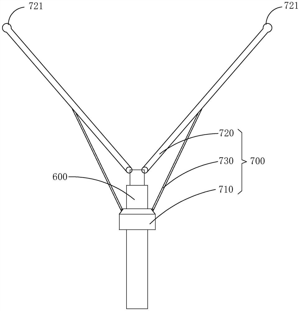
The invention discloses a pipe clamping device and a pipe cutting machine. The pipe clamping device comprises a base frame, a first clamping structure, a second clamping structure, a telescopic mechanism and a supporting and fixing mechanism, and a long-strip pipe to be machined is placed between the first clamping structure and the second clamping structure; the first clamping structure and the second clamping structure can abut against the inner side edges of the two ends of the pipe correspondingly, so that the pipe is clamped and fixed, the telescopic mechanism drives the supporting and fixing mechanism to move and stretch into the pipe, and the supporting and fixing mechanism abuts against the inner wall of the pipe so that supporting and bearing can be provided for the middle position of the pipe; therefore, shaking of the pipe is reduced, more stable clamping of the whole to-be-machined pipe is achieved, the cutting machining precision is guaranteed, the first clamping structure, the second clamping structure and the supporting and fixing mechanism all act on the inner side of the pipe, the pipe clamping and supporting occupy few pipe positions, the appearance of the pipe can be prevented from being damaged, tailings can be reduced, and the cost is saved.

Description

technical field [0001] The invention relates to the technical field of laser cutting, in particular to a pipe clamping device and a pipe cutting machine. Background technique [0002] With the rapid development of the domestic economy, the application of pipes is becoming more and more common, especially in the industrial field. Different application fields have special requirements for the thickness, length and shape of pipes. As a common pipe cutting and processing equipment, pipe machine is widely used in industrial production. [0003] When the current pipe cutting machine is processing a fixed-length pipe, in order to avoid damaging the appearance of the pipe, two clamping heads are often used to clamp and fix the inner holes at both ends of the pipe to achieve rotary cutting and drilling. However, because the pipe has a certain length, it is easily affected by external forces, and the pipe will vibrate during the rotation process, especially the middle position of the...

Claims


Application Information

Patent Timeline
IPC IPC(8): B23K26/38B23K26/70B23K101/06
CPCB23K26/38B23K26/702B23K2101/06
Inventor 吴清平
Owner 大展智能装备(广东)有限责任公司
Learn More