
Repair device and repair method for concrete drilling coring

A technology for drilling and coring and concrete, which is used in building maintenance, construction, building construction, etc., can solve the problems of insufficiency, bubble generation, material waste grouting, etc., to achieve the effect of convenient operation, avoid waste, and ensure durability.

Active Publication Date: 2022-01-11
SHANDONG JIAOTONG UNIV
View PDF7 Cites 0 Cited by
  • Summary
  • Abstract
  • Description
  • Claims
  • Application Information

AI Technical Summary

Problems solved by technology

[0005] In view of the deficiencies in the prior art, the purpose of the present invention is to provide a repairing device and repairing method for concrete drilling and coring, which can discharge the gas generated during the grouting process through the discharge mechanism, and can recycle the excess grouting material , reducing the waste of grouting materials, and solving the problems of material waste and air bubbles caused by insufficient grouting in the existing hole repair work

Method used


Image

  • Repair device and repair method for concrete drilling coring
  • Repair device and repair method for concrete drilling coring
  • Repair device and repair method for concrete drilling coring

Examples


Embodiment 1

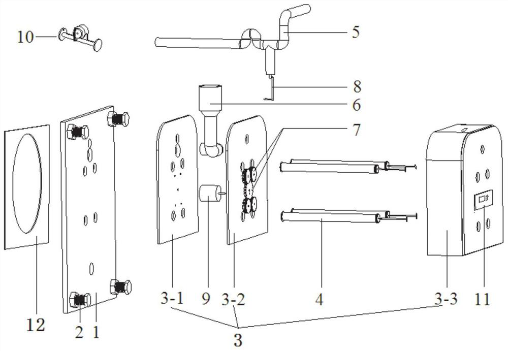
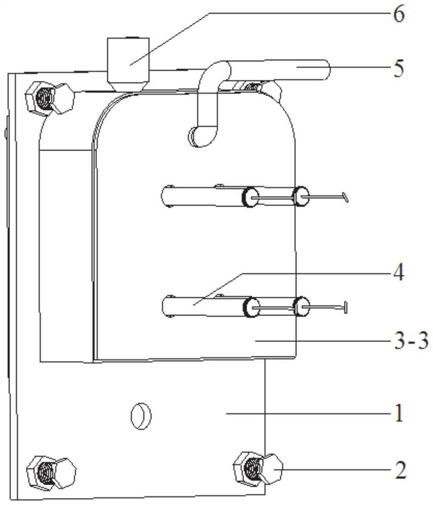
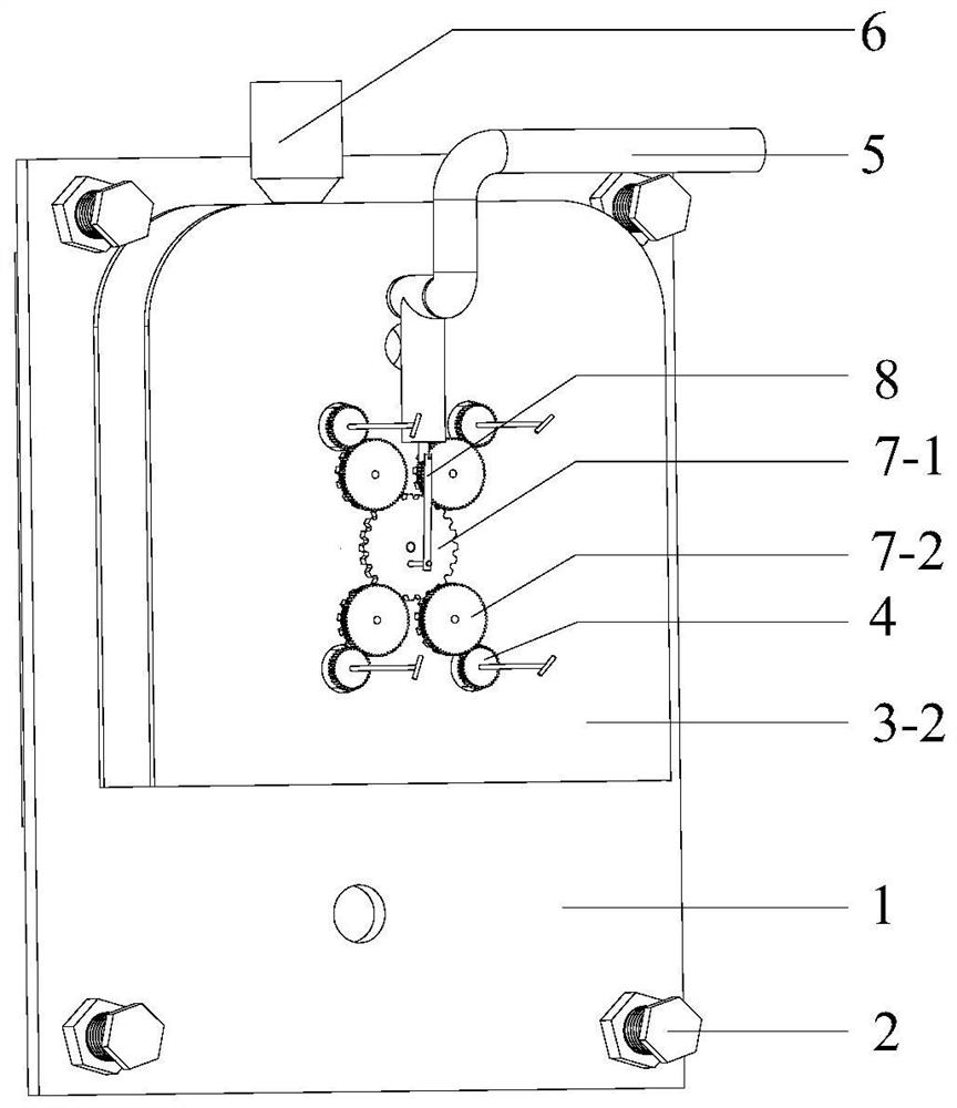
[0051] In a typical embodiment of the present invention, such as Figure 1-Figure 9 As shown, a repair device for concrete drilling and coring is proposed, including a panel 1, a fixed rod 2, a fixed plate 3, a vibrating rod 4, a discharge pipe 5, a filling pipe 6, a transmission gear set 7, and a linkage rod 8 , the first motor 9, the detector 10, the control system 11 and the rubber pad 12.

[0052] Among them, the fixing plate 3 and the rubber pad 12 are installed on both sides of the panel 1 respectively, and the rubber pad 12 is located on the side where the panel 1 is in contact with the concrete structure, which is used to reduce the damage of the panel 1 to the surface of the concrete structure, and can ensure that the panel 1 is in contact with the concrete structure. The tightness between the concrete structures, the fixed plate 3 is located on the other side of the panel 1.

[0053] The panel 1 is provided with a grouting hole 1-3, a grouting hole 1-4, a vibrating ...

Embodiment 2

[0082] In another typical embodiment of the present application, a method for repairing a repairing device for concrete drilling and coring as described in Embodiment 1 is provided. In this embodiment, the grouting material adopts epoxy mortar with certain fluidity, and the specific steps as follows:

[0083] (1) Each device is assembled and welded into shape, and the detector 10 is installed on the innermost side of the upper edge of the hole at a position away from the dumbbell-shaped rod 10-1, so as to prevent the movement of the dumbbell-shaped rod 10-1 from being restricted inside the hole and affect the detection effect;

[0084]Since the core is drilled on the side wall of the concrete structure, the direction of the hole is perpendicular to the horizontal direction of the concrete side wall, so the inner wall of the hole can be divided into the inner curved side wall of the hole and the inner vertical side wall of the hole. The innermost side of the edge refers to the ...


PUM


Abstract

The invention discloses a repair device and repair method for concrete drilling coring, and belongs to the technical field of building construction. The repair device comprises a material filling pipeline and a discharging mechanism which are both connected to a panel; the discharging mechanism comprises a linear pipeline and a curve pipeline which are connected with each other, the curve pipeline comprises an inverted U-shaped pipe section and an L-shaped pipe section which are connected into a whole, the inverted U-shaped pipe section communicates with the linear pipeline, the L-shaped pipe section is connected with a slurry pump, a first one-way ball valve is arranged at the L-shaped pipe section, and a second one-way ball valve is arranged at the inverted U-shaped pipe section.

Description

technical field [0001] The invention relates to the technical field of concrete repair, in particular to a repair device and a repair method for drilling and coring concrete. Background technique [0002] The statements herein merely provide background information related to the present invention and do not necessarily constitute prior art. [0003] With the continuous construction of concrete building structures, the drilling and coring method, as a means of testing the performance of concrete materials, is more and more applied to the actual engineering testing process. Although the drilling and coring method can effectively evaluate the performance of concrete in building structures, the holes left by drilling will also cause greater damage to the structure and affect the performance of the structure during operation. [0004] The inventors have found that, in traditional repairing of boreholes, the grouting material is usually poured directly into the hole, and after th...

Claims


Application Information

Patent Timeline
Patent Type & Authority Applications(China)
IPC IPC(8): E04G23/02G01N27/74
CPCE04G23/0203G01N27/74
Inventor 崔凤坤潘韶军刘玉芳
Owner SHANDONG JIAOTONG UNIV
Learn More