
Reverse gravel throwing device and method

A technology for throwing gravel and gravel, which is applied in the field of in-situ leaching of uranium, can solve the problems of increasing the cost of well flushing, unsealing the gravel throwing pipe and the gravel throwing device, and affecting the effect of throwing gravel, so as to ensure the pumping effect and reduce the washing rate. The effect of well cost

Pending Publication Date: 2022-01-11
BEIJING RESEARCH INSTITUTE OF CHEMICAL ENGINEERING AND METALLURGY
View PDF0 Cites 1 Cited by
  • Summary
  • Abstract
  • Description
  • Claims
  • Application Information

AI Technical Summary

Problems solved by technology

The current use of the gravel throwing device has the following disadvantages: First, the gravel throwing pipe and the gravel throwing device are not sealed, the water flow cannot completely enter the gravel throwing device, and there is a situation that the gravel is discharged back into the casing with the water flow; the second is that the gravel does not return The cover plate will rebound with the change of water flow, and the valve will not be fully opened, which will affect the effect of gravel throwing; third, some built-in filters are not equipped with sand settling pipes, which will affect the pumping when the settling sand accumulates in the filter, and also increase the washing effect. well cost

Method used

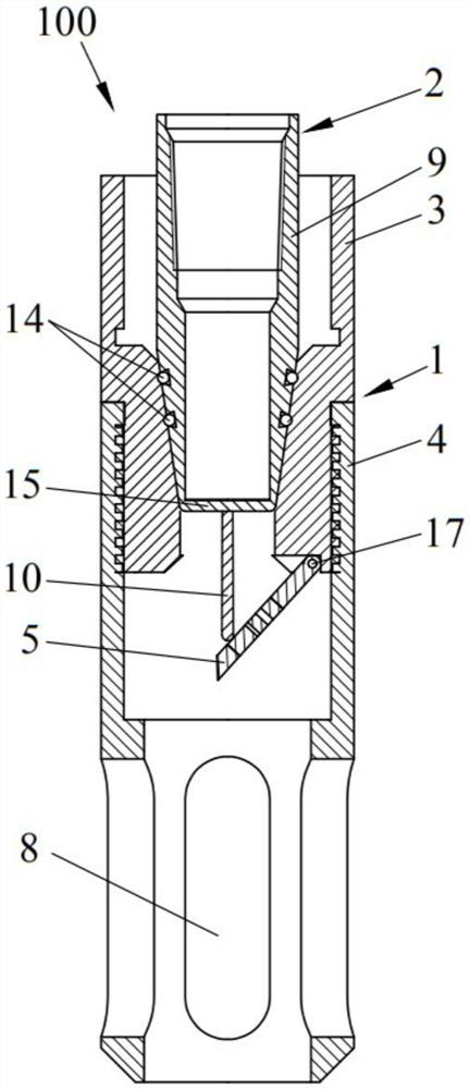
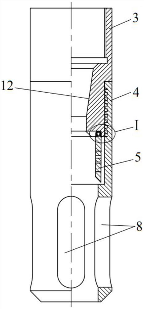

Image

  • Reverse gravel throwing device and method
  • Reverse gravel throwing device and method
  • Reverse gravel throwing device and method

Examples


Embodiment Construction

[0038] The following will clearly and completely describe the technical solutions in the embodiments of the present invention with reference to the accompanying drawings in the embodiments of the present invention. Obviously, the described embodiments are only some, not all, embodiments of the present invention. Based on the embodiments of the present invention, all other embodiments obtained by persons of ordinary skill in the art without making creative efforts belong to the protection scope of the present invention.

[0039] The object of the present invention is to provide a reverse gravel throwing device and method to solve the problems existing in the prior art, so that the gravel does not flow back, improves the effect of gravel throwing, and can avoid the accumulation of sand in the built-in filter, thereby ensuring Injection effect, reduce the cost of well cleaning.

[0040] In order to make the above objects, features and advantages of the present invention more comp...


PUM


Abstract

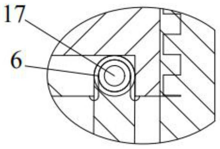
The invention discloses a reverse gravel throwing device and method. A gravel throwing valve body comprises an adapter, a lower branch pipe, a gravel non-return cover plate and a reset element; the top end of the adapter is used for being connected to a built-in filter, the bottom end of the adapter is in sealed connection with the top end of the lower branch pipe, the gravel non-return cover plate is movably connected to a port of the bottom end of the adapter, sand setting holes capable of preventing gravel from passing through are formed in the gravel non-return cover plate, the reset element can provide reset force to enable the gravel non-return cover plate to keep blocking the port of the bottom end of the adapter, and a flow guide groove is formed in the bottom end of the lower branch pipe; and the top end of a connector body is used for being in sealed connection with a gravel throwing pipe, the bottom end of the connector body is connected to a pushing rod, and when the bottom end of the connector body is inserted into the adapter and is in sealed connection with the adapter, the pushing rod can overcome the reset force of the reset element to push and open the gravel non-return cover plate. According to the reverse gravel throwing device and method, the gravel does not flow back, the gravel non-return cover plate does not rebound due to the change of water flow, the gravel throwing effect is ensured, settled sand can be prevented from being accumulated in the built-in filter, the pumping and injecting effect is ensured, and the well washing cost is reduced.

Description

technical field [0001] The invention relates to the technical field of in-situ leaching uranium mining, in particular to a reverse gravel throwing device and method, which are used for throwing gravel in in-situ leaching uranium production wells and general hydrological water wells. Background technique [0002] The in-situ leaching uranium production well is the only channel for metal mining in in-situ leaching sandstone-type uranium mines. This channel is composed of casing, filter and sand settling pipe from top to bottom. It is a working channel for the hydraulic connection between the surface and the aquifer, called the production column. [0003] The structure of the existing in-situ leaching uranium production well is basically a gravel-packed drilling structure. The gravel throwing process is to connect the sand settling pipe, filter and upper casing in sequence after the drilling is completed, and install them in the drilling; Then put a gravel injection grouting p...

Claims


Application Information

Patent Timeline
Patent Type & Authority Applications(China)
IPC IPC(8): E21B43/04E21B17/02E21B34/06
CPCE21B43/04E21B17/02E21B34/06
Inventor 杨立志李召坤阳奕汉杜志明
Owner BEIJING RESEARCH INSTITUTE OF CHEMICAL ENGINEERING AND METALLURGY
Learn More