
Universal flow channel collector

A collector and flow channel technology, which is applied in the field of pipeline valves, can solve the problems that pipeline impurities cannot be removed in time, installation is not convenient, and space is occupied.

Pending Publication Date: 2022-01-11
艾肯(江苏)工业技术有限公司
View PDF8 Cites 0 Cited by
  • Summary
  • Abstract
  • Description
  • Claims
  • Application Information

AI Technical Summary

Problems solved by technology

[0004] The purpose of the present invention is to provide a universal flow channel collector, which aims to improve the existing pipeline valve, which has a simple structure and can only simply play the role of controlling on-off in the actual use process. There is no valve inside the valve body. Corresponding filter mechanism, so that when impurities appear in the pipeline, it cannot be removed in time. At the same time, most of the traditional pipeline valves separate the drain flow channel and the exhaust flow channel, so that it is not convenient to install when both are needed at the same time. Occupies space, and the installation direction of the traditional pipeline valve is fixed, and the installation angle cannot be adjusted flexibly according to the needs, which is not convenient for users

Method used


Image

  • Universal flow channel collector
  • Universal flow channel collector
  • Universal flow channel collector

Examples


Embodiment Construction

[0030]In order to make the purpose, technical solutions and advantages of the embodiments of the present invention clearer, the technical solutions in the embodiments of the present invention will be clearly and completely described below in conjunction with the accompanying drawings in the embodiments of the present invention. Obviously, the described embodiments It is some embodiments of the present invention, but not all of them. Based on the implementation manners in the present invention, all other implementation manners obtained by persons of ordinary skill in the art without creative efforts fall within the protection scope of the present invention. Accordingly, the following detailed description of the embodiments of the invention provided in the accompanying drawings is not intended to limit the scope of the claimed invention, but merely represents selected embodiments of the invention. Based on the implementation manners in the present invention, all other implementa...


PUM


Abstract

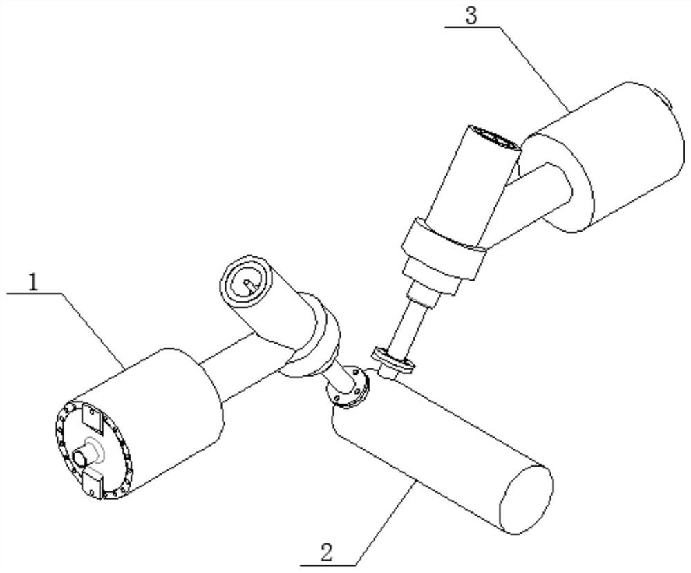
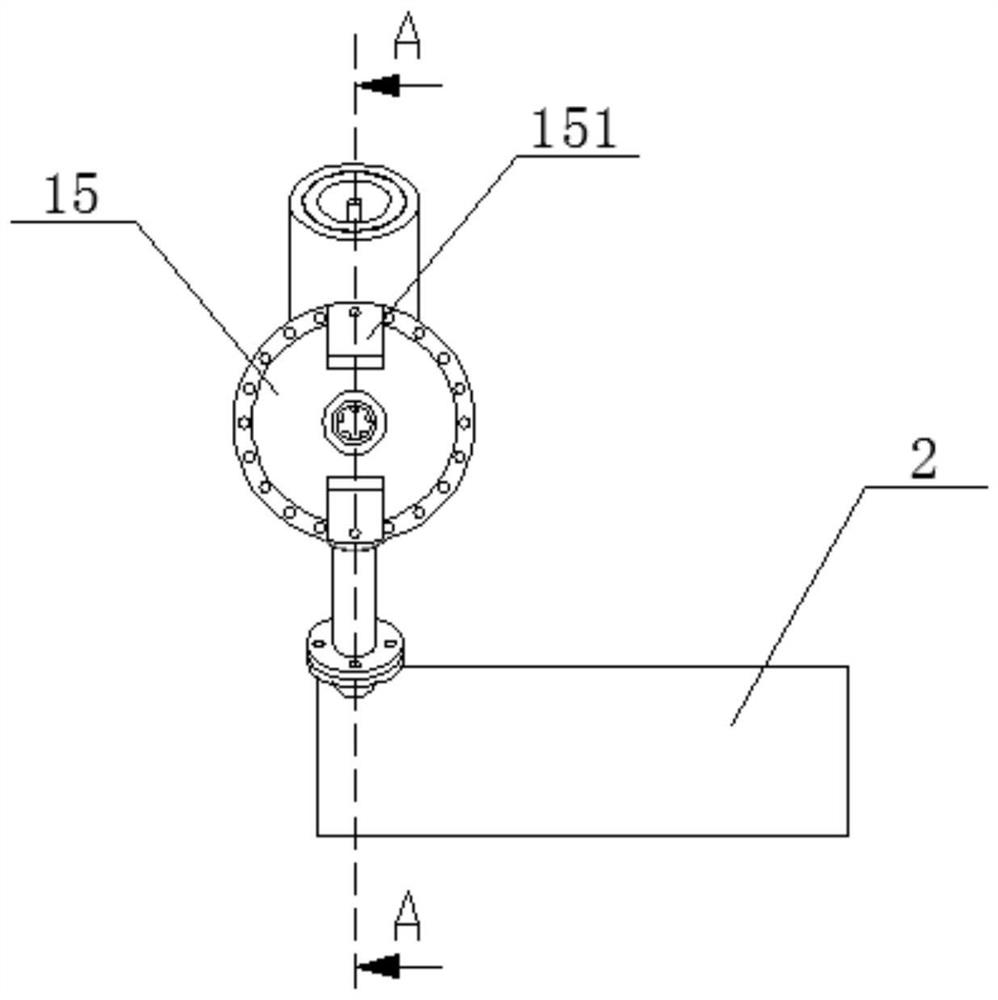
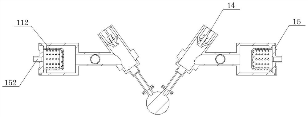
The invention discloses a universal flow channel collector. The universal flow channel collector comprises an inflow valve, a trap valve and a drainage valve, wherein the inflow valve and the drainage valve are symmetrically arranged on the trap valve, the inflow valve and the drainage valve are both fixedly connected with the trap valve in a sealed mode, each of the inflow valve and the drainage valve comprises a filtering mechanism and a plunger valve, the plunger valves are installed at the head portions of the filtering mechanisms, and fixedly connected with the filtering mechanisms, and flow guiding mechanisms are installed on the head portions of the plunger valves, and fixedly connected with the plunger valves. While needing to use, a user is guaranteed to stably connect the inflow valve and the drainage valve with the trap valve after stably assembling the inflow valve and the drainage valve, and in this way, the energy-saving trap valve and the economical and convenient valves can be combined into a single connection joint, and after the joint is installed on a pipeline, integration of drainage and exhaust can be realized at the same time.

Description

technical field [0001] The invention relates to the technical field of pipeline valves, in particular to a universal channel collector. Background technique [0002] Various pipeline valves are often used in the process of traditional fluid transmission pipelines. Users can control the flow direction, flow rate and on-off of liquid through various pipeline valves, and plunger valves are the most common. A valve body, the plunger valve is composed of valve body, valve cover, valve stem, plunger, hole frame, sealing ring, hand wheel and other parts. When the hand wheel rotates, the valve stem drives the plunger up and down in the middle of the hole frame The reciprocating motion is used to complete the opening and closing function of the valve. At the same time, when controlling the liquid with steam, the steam trap is often used. Its basic function is to discharge the condensed water, air and carbon dioxide gas in the steam system as soon as possible. , while automatically p...

Claims


Application Information

Patent Timeline
Patent Type & Authority Applications(China)
IPC IPC(8): F16K11/20F16K27/00F16K31/60F16T1/38B01D35/04
CPCF16K11/20F16K27/00F16K31/60F16T1/38B01D35/04
Inventor 王勇飞郝刚姜敏伟
Owner 艾肯(江苏)工业技术有限公司
Learn More