Solar lighting street lamp

A technology for lighting street lamps and solar energy, applied in the field of street lamps, can solve the problems of not being able to receive sunlight to the maximum extent, unable to track solar panels, lack of clutch devices, etc., and achieve the effect of preventing it from being broken by wind

Pending Publication Date: 2022-01-11
安徽安发特交通工程集团有限公司
View PDF1 Cites 0 Cited by
  • Summary
  • Abstract
  • Description
  • Claims
  • Application Information

AI Technical Summary

Problems solved by technology

The patent of Chinese Patent Notification No. CN214119906U discloses a solar street lamp, including a base, the top of the base is provided with a light pole with adjustable height, the top of the light pole is fixed with a support rod, and the top of the support rod is fixed with a mounting The installation box is provided with a battery, the top of the installation box is fixed with a bracket, and the tilted solar panel is fixed on the bracket, and the battery is powered by the solar panel, and the upper part of the support rod is fixed. A mounting plate is provided, and angle-adjustable lighting lamps are installed on both sides of the mounting board, and a power mechanism for driving the angle adjustment of the lighting lamps is provided on the installation box, and the power mechanism and the lighting lamps are connected with each other. The battery is electrically connected. This invention makes street lamps easy to maintain, easy to save energy, and easy to adjust the lighting range. At that time, the solar panel cannot track the position of the sun, so that it cannot receive sunlight to the greatest extent, and it lacks a clutch device, so the solar panel is easy to use. blown off by the wind

Method used


Image

  • Solar lighting street lamp
  • Solar lighting street lamp
  • Solar lighting street lamp

Examples


Embodiment 1

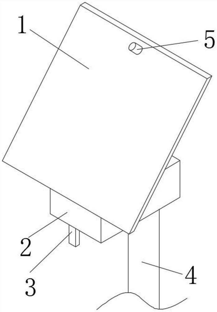
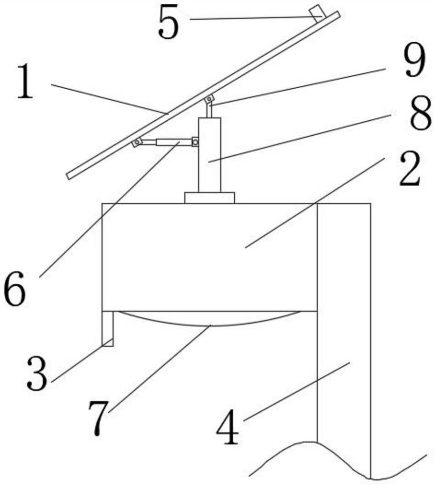
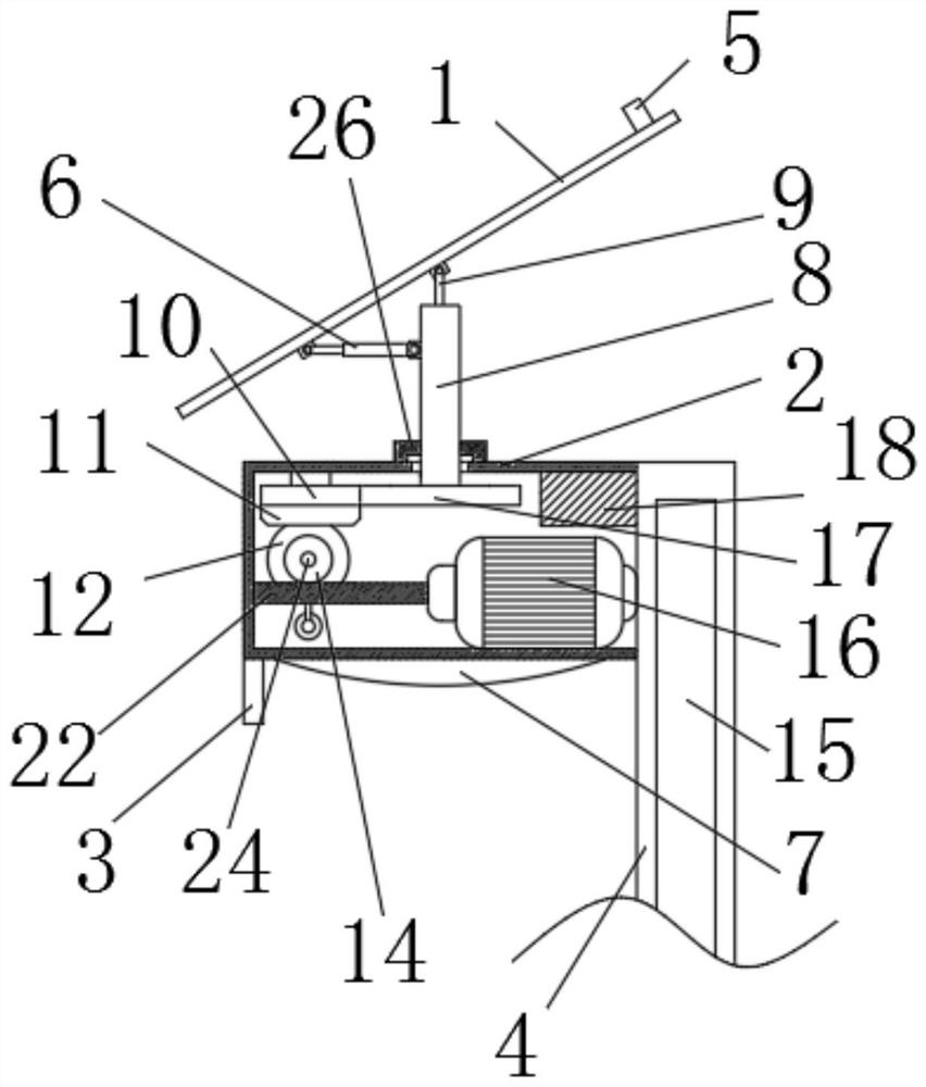
[0036] refer to Figure 1-4 , the present invention provides a solar lighting street lamp, comprising a column 4, a battery 15 is arranged inside the column 4, a control box 2 is arranged on the left side of the upper part of the column 4, a processor 18 is arranged on the inner top wall of the right side of the control box 2, and a control box 2 The lower part of the right side is provided with a reduction motor 16, and the left side driving end of the reduction motor 16 is provided with a worm screw 22, and the inner wall of the front side of the control box 2 is rotatably connected with a first connecting rod 24, and the outer periphery of the first connecting rod 24 is provided with a worm wheel 14. The outer periphery of the rear side of the connecting rod 24 is provided with evenly distributed clamping blocks 21, the middle part of the inner wall of the rear side of the control box 2 is rotatably connected with a second connecting rod 25, and the outer periphery of the mi...

Embodiment 2

[0039] refer to Figure 1-4 The difference between this embodiment and the above-mentioned embodiment is that a second hydraulic rod 13 is provided on the lower part of the inner wall of the rear side of the control box 2, and a push rod 23 is provided at the front end of the second hydraulic rod 13, and the upper end of the push rod 23 is rotatably connected with a casing 19, Evenly distributed card slots 20 are arranged inside the casing 19, and the middle part of the inner wall of the rear side of the control box 2 is rotatably connected with a second connecting rod 25, and the outer periphery of the middle part of the second connecting rod 25 is provided with a second bevel gear 12. Evenly distributed clamping blocks 21 are arranged on the outer periphery of the side, the first spur gear 10 is rotatably connected to the inner top wall on the left side of the control box 2, the first bevel gear 11 is arranged on the lower part of the first spur gear 10, and the upper middle ...

Embodiment 3

[0042] refer to Figure 1-4 The difference between this embodiment and the above-mentioned embodiments is that the clamping blocks 21 are all slidably connected inside the clamping groove 20, the clamping groove 20 is arranged inside the casing 19, and the sleeve 19 is rotatably connected to the upper part of the push rod 23, and is clamped by the clamping groove 20. Hold all the blocks 21 so that when the first connecting rod 24 rotates, the second connecting rod 25 rotates together, and the push rod 23 can push the sleeve 19 to move back and forth, so that the blocks 21 on the first connecting rod 24 can be disengaged from the card. Groove 20, control box 2 right side lower part is provided with decelerating motor 16, and decelerating motor 16 left side drive end is provided with worm screw 22, and worm screw 22 upper side meshingly is connected with worm wheel 14, drives worm screw 22 to rotate by decelerating motor 16, makes worm screw 22 drive The worm wheel 14 rotates, t...


PUM


Abstract

The invention relates to the technical field of street lamps and discloses a solar lighting street lamp which comprises a stand column, a storage battery is arranged in the stand column, a control box is arranged on the left side of the upper portion of the stand column, a processor is arranged on the inner top wall of the right side of the control box, and a first connecting rod is rotationally connected to the inner wall of the front side of the control box. A worm gear is arranged on the periphery of the middle of the first connecting rod, clamping blocks which are evenly distributed are arranged on the periphery of the rear side of the first connecting rod, a second hydraulic rod is arranged on the lower portion of the inner wall of the rear side of the control box, a push rod is arranged at the front end of the second hydraulic rod, and a second connecting rod is rotationally connected to the middle of the inner wall of the rear side of the control box. According to the invention, the angle of the solar panel can be adjusted by driving a gear motor and a first hydraulic rod, so that the solar panel can receive sunlight to the greatest extent, and meanwhile, the solar panel can rotate along with the wind by driving the second hydraulic rod, so that the solar panel is protected to a great extent.

Description

technical field [0001] The invention relates to the technical field of street lights, in particular to a solar street light. Background technique [0002] Since the birth of life on earth, it has mainly survived on the heat radiation energy provided by the sun. Since ancient times, humans have also known to use sunlight to dry objects and use it as a method of making food, such as making salt and drying salted fish. The fossil fuels are decreasing day by day. Under the circumstances, solar energy has become an important part of energy used by human beings, and it has been continuously developed. There are two ways to use solar energy: photothermal conversion and photoelectric conversion. Including wind energy, chemical energy, water energy, etc. on the earth. The patent of Chinese Patent Notification No. CN214119906U discloses a solar street lamp, including a base, the top of the base is provided with a light pole with adjustable height, the top of the light pole is fixed w...

Claims


Application Information

Patent Timeline
Patent Type & Authority Applications(China)
IPC IPC(8): F21S9/03H02S20/32F21W131/103
CPCF21S9/035H02S20/32F21W2131/103Y02E10/50Y02B20/72
Inventor 李秀萍
Owner 安徽安发特交通工程集团有限公司
Why Eureka
Try Eureka