Antenna for communication equipment

A technology for communication equipment and communication antennas, applied in the directions of antennas, rotating antennas, folding antennas, etc., can solve the problems of unfavorable staff maintenance, communication antennas are easy to be broken, etc., and achieve the effect of improving the protection performance

Active Publication Date: 2021-11-30
江苏互航网络科技有限公司
View PDF5 Cites 0 Cited by
  • Summary
  • Abstract
  • Description
  • Claims
  • Application Information

AI Technical Summary

Problems solved by technology

Communication antennas are generally installed outdoors to work. However, in extreme weather such as typhoons, communication antennas are easily broken, and in actual use, communication antennas are generally installed at high places, which is not conducive to staff maintenance

Method used


Image

  • Antenna for communication equipment
  • Antenna for communication equipment
  • Antenna for communication equipment

Examples


Embodiment 1

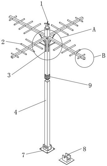
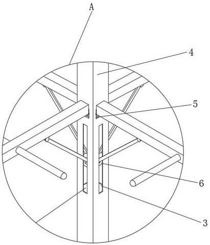
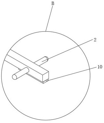
[0032]In order to fold the communication antenna 2 to reduce its windward side, an anemometer 1 is fixedly installed on the top of the antenna bracket 4, and a connecting mechanism 9 is fixedly installed in the middle position in the antenna bracket 4. The connecting mechanism 9 includes a mechanism shell 901, a connecting rivet 902, an electromagnetic Iron 903, connecting feet 904 and connecting holes 905, the top edge of the antenna bracket 4 is provided with a lifting gap 3, and a folding mechanism 6 is installed at the lifting gap 3 in the antenna bracket 4, and the folding mechanism 6 includes a first rotating shaft 601, a supporting pole 602, the second rotating shaft 603, the movable gap 604, the movable block 605 and the hydraulic push rod 606, the communication antenna 2 is connected to the end of the support rod 602, the hinge 5 is connected to one end of the communication antenna 2, and the other end of the communication antenna 2 is fixedly installed with a connectio...

Embodiment 2

[0034] In order to make things easier for the staff to overhaul the communication antenna 2, the bottom end of the antenna support 4 is fixedly provided with a support base 7, and the support base 7 includes a grounding screw 701, a bogie body 702, a limit screw frame 703, a movable rotating shaft 704, a positioning screw 705 and The positioning base 706, the bottom of the antenna support 4 is located on one side of the support base 7 and a limit mechanism 8 is provided. The limit mechanism 8 includes a limit base 801, a limit frame body 802, a limit screw 803, a limit screw hole 804 and a rubber gasket 805, the positioning base 706 is arranged at the bottom of the antenna bracket 4, the upper surface of the positioning base 706 is located at the four corners and is provided with grounding screw holes 701, the upper surface of the positioning base 706 is located in the middle position and fixedly installed with a bogie body 702, and the bogie body 702 is movable. There is a mov...


PUM


Abstract

The invention discloses an antenna for communication equipment, which comprises an antenna support, an anemometer, a communication antenna, a folding mechanism, a support base, a limit mechanism and a connection mechanism. The bottom end of the antenna support is fixedly provided with a support base, and the support base It includes a grounding screw hole, a bogie body, a limit screw frame, a movable shaft, a positioning screw hole and a positioning base. The bottom of the antenna support is located on one side of the support base to set a limit mechanism, and the antenna support is fixedly installed in the middle position. The connection mechanism, the top edge of the antenna bracket is provided with a lifting gap, and a folding mechanism is installed at the lifting gap in the antenna bracket, and the folding mechanism includes a first rotating shaft, a supporting rod, a second rotating shaft, a movable gap, blocks and hydraulic push rods. The antenna for communication equipment of the present invention belongs to the field of communication equipment, has good anti-typhoon performance, and is convenient for users to overhaul.

Description

technical field [0001] The invention relates to the field of communication equipment, in particular to an antenna for communication equipment. Background technique [0002] The antenna is an important part of the communication system, and it is the input and output channel of the radio frequency signal. The performance of the antenna system affects the performance of the entire communication system. An antenna is a transformer that transforms a guided wave propagating on a transmission line into an electromagnetic wave propagating in an unbounded medium, or vice versa. A component used in radio equipment to transmit or receive electromagnetic waves. Engineering systems such as radio communication, broadcasting, television, radar, navigation, electronic countermeasures, remote sensing, and radio astronomy, which use electromagnetic waves to transmit information, rely on antennas to work. Communication antennas are generally installed outdoors to work. However, in extreme we...

Claims


Application Information

Patent Timeline
Patent Type & Authority Patents(China)
IPC IPC(8): H01Q1/00H01Q1/08H01Q1/12
CPCH01Q1/005H01Q1/084H01Q1/12H01Q1/1235
Inventor 庄晓玲
Owner 江苏互航网络科技有限公司
Why Eureka
Try Eureka