
Device for measuring cross-ball distance

A technology that spans the ball distance and measures the ball. It is used in measurement devices, mechanical measurement devices, and mechanical devices. It can solve the problems of difficulty in ensuring accuracy and increase the radiation dose of personnel, and achieve the effect of rapid measurement.

Pending Publication Date: 2022-01-11
CNNC NUCLEAR POWER OPERATION MANAGEMENT +1
View PDF0 Cites 0 Cited by
  • Summary
  • Abstract
  • Description
  • Claims
  • Application Information

AI Technical Summary

Problems solved by technology

[0006] According to the structure of the fuel channel and the high-radiation environment on site, directly using the measuring ball or measuring rod to carry out the measurement is not only difficult to guarantee the accuracy, but also greatly increases the radiation dose of personnel

Method used


Image

  • Device for measuring cross-ball distance
  • Device for measuring cross-ball distance
  • Device for measuring cross-ball distance

Examples


Embodiment Construction

[0038] Although the device for measuring cross-ball distance of the present invention can be implemented in many different ways, exemplary embodiments will be described in detail herein with reference to the accompanying drawings. The structure of the device for measuring the over-the-ball distance is exemplified, and it is not intended to limit the protection scope of the present invention to the exemplary embodiment. Accordingly, the drawings and description of the detailed description are to be considered as illustrative in nature of the invention and not as limiting.

[0039] In the description of the present invention, it should be noted that the orientation or positional relationship indicated by the terms "up", "down", "left", "right", "inside", "outside" and "horizontal" herein are Based on the orientation or positional relationship shown in the drawings, it is only for the convenience of describing the present invention and simplifying the description, and does not in...


PUM


Abstract

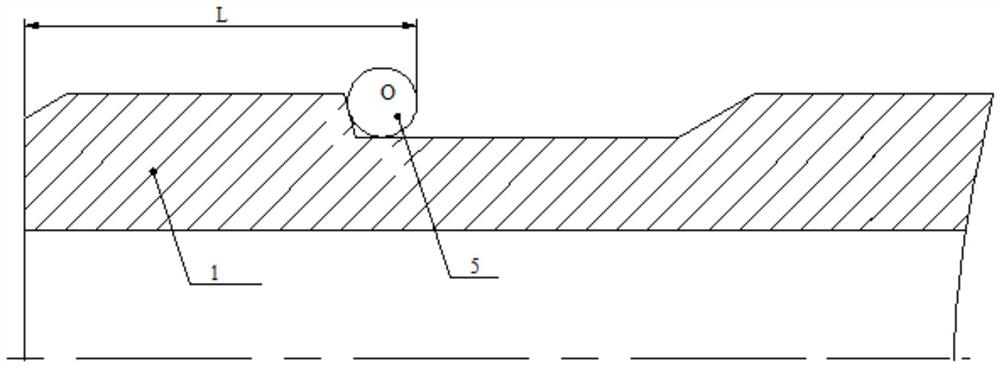
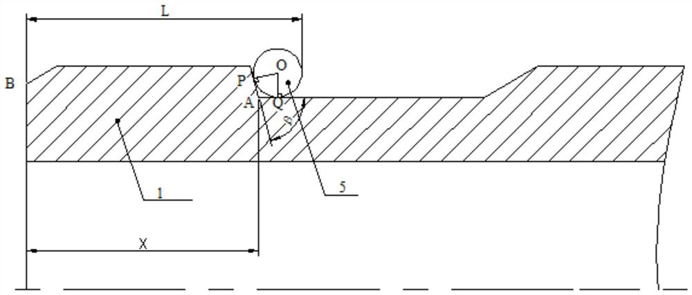
The invention provides a device for measuring a cross-ball distance, which comprises a measuring rod, one end of the measuring rod is connected with a zero-setting dial indicator, the other end of the measuring rod is connected with a measuring base, a measuring head of the dial indicator faces the measuring base, the measuring base is provided with a special-shaped hole, and a measuring ball is arranged in the special-shaped hole. The bottom of the measuring ball protrudes outwards relative to the bottom face of the measuring base, and a notch is formed in a corner formed by the inner side face of the measuring base and the bottom face to expose the measuring ball. The device for measuring the cross-ball distance provided by the invention can accurately and quickly measure the axial cross-ball distance from the conical surface step to the end surface of a fuel channel end part.

Description

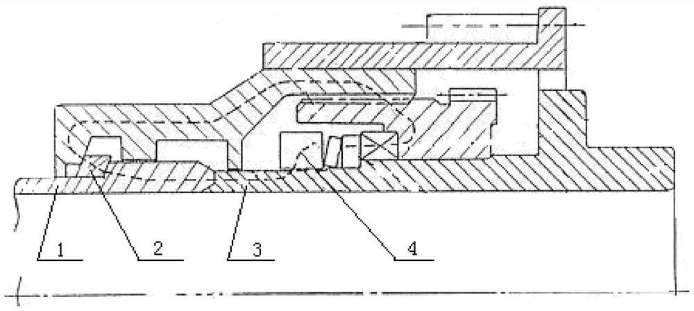
technical field [0001] The invention relates to the technical field of nuclear industry equipment measurement, in particular to a device for measuring the cross-ball distance. Background technique [0002] The fuel channel end parts of the heavy water reactor constitute the main heat transfer system of the primary circuit, which has the functions of positioning and supporting the fuel rod bundle, and sealing the high-pressure and high-temperature heavy water coolant. Such as figure 1 As shown, the loading and unloading machine for refueling relies on the clamping force generated by the clamping mechanism of the nozzle assembly so that the wedge-shaped claw 2 is clamped on the conical surface step of the fuel channel, and the central support cylinder 3 and the end part 1 of the fuel channel are tightly attached to each other. At the same time, rely on the sealing surface of the fuel channel end face, the static sealing ring and the sealing surface of the central support cyli...

Claims


Application Information

Patent Timeline
IPC IPC(8): G01B5/02G01B5/14
CPCG01B5/02G01B5/14
Inventor 李平原高照曹烽华苗润泽江东飞蒋军建王晓峰
Owner CNNC NUCLEAR POWER OPERATION MANAGEMENT
Learn More