Inertial measurement system error separation method based on centrifugal machine large overload excitation

An inertial measurement and system error technology, which is applied in the aviation field of aerospace and high-precision inertial navigation, can solve problems such as the separation of inertial device errors, and achieve improved accuracy, robust stability, high confidence, and noise elimination. Effect

Pending Publication Date: 2022-01-11
BEIJING INST OF AEROSPACE CONTROL DEVICES
View PDF0 Cites 4 Cited by
  • Summary
  • Abstract
  • Description
  • Claims
  • Application Information

AI Technical Summary

Problems solved by technology

However, in the actual application process, the speed stability of the developed centrifuge can only reach 1×10 -4 , cannot meet the requirements of inertial device error separation

Method used


Image

  • Inertial measurement system error separation method based on centrifugal machine large overload excitation
  • Inertial measurement system error separation method based on centrifugal machine large overload excitation
  • Inertial measurement system error separation method based on centrifugal machine large overload excitation

Examples


Embodiment

[0130] In order to illustrate the inertial measurement system error separation method based on the large overload excitation of the centrifuge provided by the present invention, the preferred embodiment is:

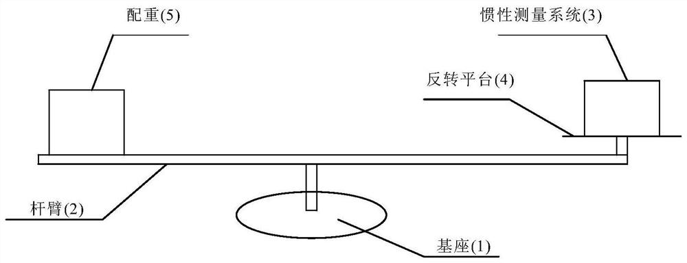
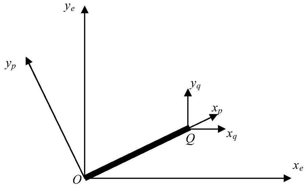
[0131] Suppose the arm length of the centrifuge is 2R=6m, and the inertial measurement system is placed on the reverse platform of the centrifuge, such as figure 1 shown. The relationship among centrifuge base, lever arm and inverted platform coordinate system is as follows: figure 2 shown.

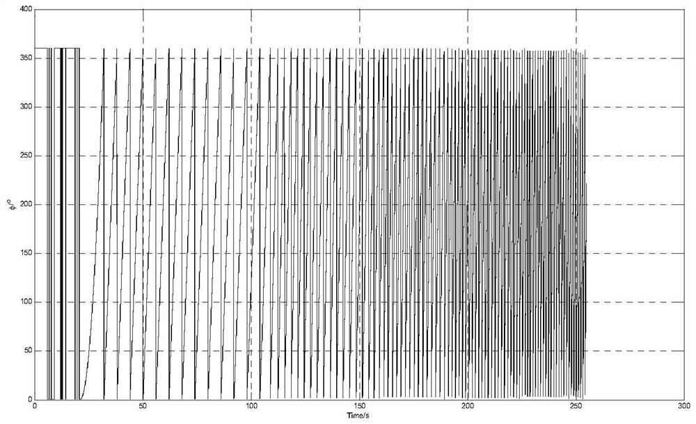
[0132] In a certain test, the sampling time of the rotation angle of the centrifuge is ΔT=0.02s, the running time is 255s, and the total number of data N=12750. The rotation angle φ and the angular velocity ω are respectively as image 3 and Figure 4 shown. Use the formula

[0133]

[0134] The calculated movement trajectory of the centrifuge lever arm relative to the base coordinate system with time is shown in Figure 5 (a) and Figure 5 (b), and synthesized to Ox e the y...


PUM


Abstract

The invention discloses an inertial measurement system error separation method based on centrifugal machine large overload excitation, which comprises the following steps: by utilizing the characteristic that the length of a centrifugal machine lever arm is not changed and combining a rotation angle of the centrifugal machine lever arm in a rotation process, obtaining a movement track of an inertial measurement system mounted on the lever arm; in addition, obtaining a motion track with an error by performing navigation calculation on the apparent acceleration of the inertial measurement system, wherein the error is mainly caused by measurement errors of a gyroscope and an accelerometer; by comparing the difference values of the two tracks, separating various error coefficients of the inertial measurement system by adopting a least square method, and improving the precision of inertial navigation through error compensation.

Description

technical field [0001] The invention relates to an error separation method of an inertial measurement system based on centrifuge excitation, in particular to an error calibration and compensation method of a dynamic installation error matrix, which is mainly used in the aviation and aerospace fields of high-precision inertial navigation. Background technique [0002] Inertial navigation is widely used in the fields of missiles, aircraft, ships and weapons. Its main function is to determine the position, velocity and attitude information of the carrier relative to the navigation system in real time. In the process of realizing the above navigation functions, the accuracy of inertial devices (including gyroscopes and accelerometers) directly determines the accuracy of attitude, position and velocity. In order to achieve high-precision navigation, the accuracy of the accelerometer must be improved from the hardware, but because it involves basic subjects such as materials and t...

Claims


Application Information

Patent Timeline
Patent Type & Authority Applications(China)
IPC IPC(8): G01C21/16
CPCG01C21/183
Inventor 魏宗康
Owner BEIJING INST OF AEROSPACE CONTROL DEVICES
Why Eureka
Try Eureka