
Speed measuring device for transmission input shaft

A speed measuring device and input shaft technology, applied in the direction of measuring device, speed/acceleration/shock measurement, speed/acceleration/shock meter detailed information, etc. The effect of improving accuracy and reducing errors

Pending Publication Date: 2022-01-11
王水英
View PDF1 Cites 0 Cited by
  • Summary
  • Abstract
  • Description
  • Claims
  • Application Information

AI Technical Summary

Problems solved by technology

Among them, the existing measurement of the speed of the input shaft of the transmission generally adopts an indirect measurement method, and the speed of the input shaft is obtained through the conversion of the sensor to measure the speed of the intermediate shaft. However, there will be conversion errors in this measurement method, which makes the measurement of the speed of the transmission input shaft inaccurate
The prior art publication No. CN111812349A provides a speed measuring device for the input shaft of a transmission. The device is provided with an induction coil, the induction coil follows the rotation of the input shaft and the planetary carrier, and a plurality of magnets are arranged on the ring base of the induction coil, and the sensor detects The rotational speed of the magnet, and then the rotational speed of the input shaft is obtained, so that the input shaft rotates smoothly. Although the device has many beneficial effects, the following problems still exist: the device measures the input shaft by setting the induction coil and the magnet, and the device does not operate When in use, the detection chamber will always be exposed to the outside, causing other foreign matter or dust to enter, which not only affects the formation of the magnetic field, but also affects the speed of the input shaft due to friction. damage

Method used

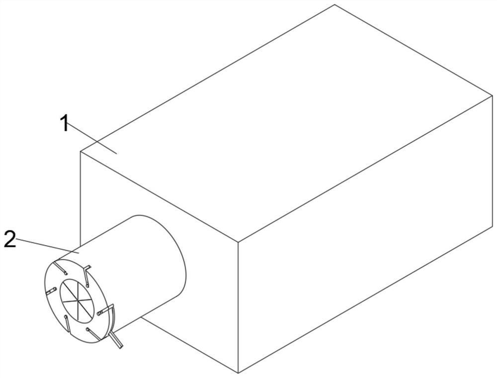
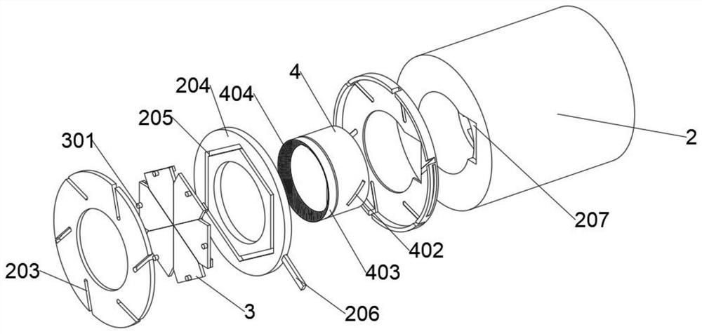
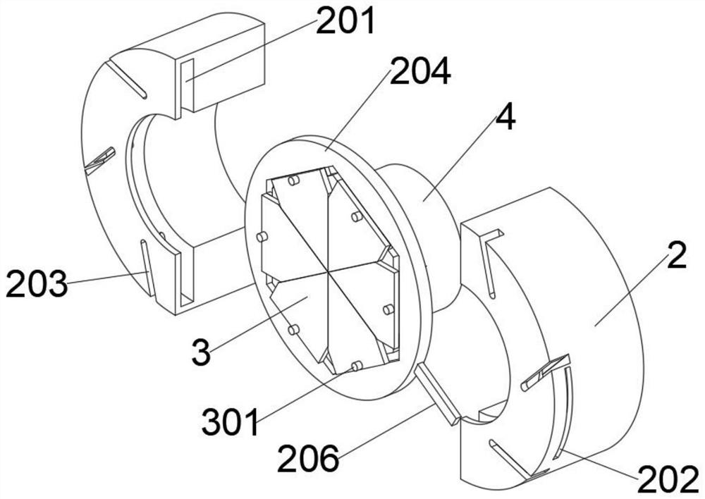

Image

  • Speed measuring device for transmission input shaft
  • Speed measuring device for transmission input shaft
  • Speed measuring device for transmission input shaft

Examples


Embodiment Construction

[0028] In describing the present invention, it should be understood that the terms "center", "longitudinal", "transverse", "length", "width", "thickness", "upper", "lower", "front", " Orientation indicated by rear, left, right, vertical, horizontal, top, bottom, inside, outside, clockwise, counterclockwise, etc. The positional relationship is based on the orientation or positional relationship shown in the drawings, and is only for the convenience of describing the present invention and simplifying the description, rather than indicating or implying that the referred device or element must have a specific orientation, be constructed and operated in a specific orientation, Therefore, it should not be construed as limiting the invention.

[0029] In the description of the present invention, "plurality" means two or more, unless otherwise specifically defined.

[0030] In the description of the present invention, it should be noted that, unless otherwise specified and limited, t...


PUM


Abstract

The invention discloses a speed measuring device for a transmission input shaft, and belongs to the technical field of automatic transmissions. The speed measuring device comprises a speed measuring body. The protective sleeve is arranged on the front side of a speed measuring body, a circular cavity is formed in the front end in the protective sleeve, and an adjusting groove extending into the circular cavity is formed in the circumferential wall face of the protective sleeve; a plurality of square through grooves penetrating to the outside of the protective sleeve are annularly formed in the front side of the circumferential wall face of the circular cavity at equal intervals, a plurality of triangular sealing blocks are annularly arranged on the front side of the hollow rotating disc at equal intervals, limiting rods are arranged at the positions, close to the edges, of the middles of the front sides of the triangular sealing blocks, and an empty groove is formed in one side of the middle position in the protective sleeve. The structures tightly cooperate, the triangular sealing blocks can be combined and closed through the rotating handle when the device is not used, so that the conditions that the detection cavity is always exposed outside, other foreign matters or dust enters the detection cavity, the formation of a magnetic field is influenced, and the rotating speed of the input shaft is influenced due to friction are effectively avoided, the detection accuracy is improved, and errors are reduced.

Description

technical field [0001] The present invention relates to the technical field of automatic transmission, and more particularly, relates to a speed measuring device for an input shaft of a transmission. Background technique [0002] The automobile transmission is a set of transmission devices used to coordinate the engine speed and the actual driving speed of the wheels, so as to realize the transmission of different gear speeds. Among them, the existing measurement of the speed of the input shaft of the transmission generally adopts an indirect measurement method, and the speed of the input shaft is obtained through the conversion of the sensor to measure the speed of the intermediate shaft. However, there will be conversion errors in this measurement method, which makes the measurement of the speed of the transmission input shaft inaccurate . The prior art publication No. CN111812349A provides a speed measuring device for the input shaft of a transmission. The device is prov...

Claims


Application Information

Patent Timeline
IPC IPC(8): G01P1/02G01P1/00
CPCG01P1/026G01P1/00
Inventor 王水英
Owner 王水英
Learn More