
High-rigidity honing device

A high-rigidity, honing technology, applied in the direction of abrasive surface adjustment devices, grinding/polishing safety devices, honing machine tools, etc., can solve the problems that the position accuracy of holes and other surfaces cannot be improved, and different workpieces cannot be supported and adjusted, so as to avoid The effect of tilting, saving time and increasing work efficiency

Pending Publication Date: 2022-01-14
AVIC POWER ZHUZHOU AVIATION PARTS MFG
View PDF11 Cites 0 Cited by
  • Summary
  • Abstract
  • Description
  • Claims
  • Application Information

AI Technical Summary

Problems solved by technology

[0002] Honing is low-speed grinding. The grinding head and the part are ground in contact with the arc surface. It is a high-efficiency grinding method that improves the dimensional accuracy, geometric shape accuracy and surface roughness of the part. Under certain conditions, it can also process flat, Outer circular surface, spherical surface, tooth surface, etc.; can effectively improve dimensional accuracy, shape accuracy and reduce Ra value, but cannot improve the position accuracy of holes and other surfaces
[0003] The honing machine is an important processing equipment. It needs to complete the processing operation through the honing head during processing. The honing head in the prior art has the characteristics of high rigidity, which can complete the workpiece processing more effectively. Most of the workpieces that need honing processing are mostly cylindrical. , by inserting the honing head into the inner wall of the workpiece for processing, but the ordinary workpiece is placed through the bushing, although it can support the workpiece, it cannot be adjusted according to the specifications of the workpiece, and there will be problems that it cannot support different workpieces

Method used


Image

  • High-rigidity honing device
  • High-rigidity honing device
  • High-rigidity honing device

Examples


Embodiment Construction

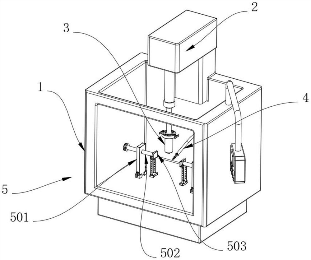
[0032] see Figure 1-9 , the present invention provides a technical solution: a high-rigidity honing device includes a body 1 and a clamping device 5, the surface of the body 1 is slidably connected to a driver 2, the bottom end of the driver 2 is installed with a grinding rod 3, and the inner wall of the body 1 is fixed. The spray head 4 is installed, the surface of the body 1 is provided with two clamping devices 5, the surface of the spray head 4 is provided with a shielding device 6, and the surface of the polishing rod 3 is provided with a cleaning device 7.

[0033] Let's talk about the specific settings and functions of its clamping device 5, shielding device 6 and cleaning device 7 in detail below.

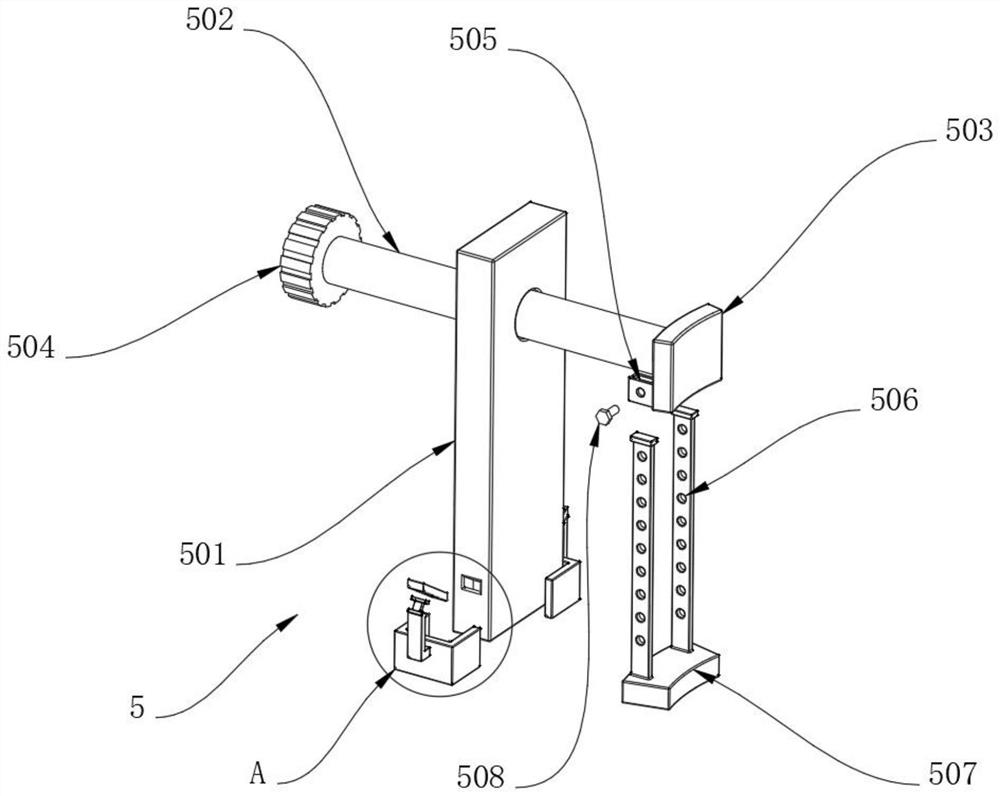
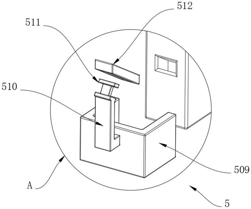
[0034] In this embodiment: the clamping device 5 includes a support plate 501, the bottom end of the support plate 501 is fixed to the inner wall of the body 1, the inner wall of the support plate 501 is threadedly connected with a threaded rod 502, and the side wall of th...


PUM


Abstract

The invention relates to the technical field of honing machines, in particular to a high-rigidity honing device. The high-rigidity honing device comprises a machine body and clamping devices, a driver is slidably connected to the surface of the machine body, a grinding rod is installed at the bottom end of the driver, a spray head is fixedly installed on the inner wall of the machine body, the two clamping devices are arranged on the surface of the machine body, the clamping devices comprise supporting plates, the bottom ends of the supporting plates are fixedly installed on the inner wall of the machine body, the inner walls of the supporting plates are in threaded connection with threaded rods, two placing blocks are fixedly installed at the positions, close to the supporting plates, of the inner wall of the machine body, a cleaning device is arranged on the surface of the grinding rod and comprises a first placing ring, the first placing ring is located on the outer surface of the grinding rod, and the side wall of the first placing ring is movably connected with a second placing ring. According to the high-rigidity honing device, the problems that a common workpiece is placed through a lining, although the workpiece can be supported, adjustment cannot be conducted according to the specification of the workpiece, and different workpieces may not be supported are solved.

Description

technical field [0001] The invention relates to the technical field of honing machines, in particular to a high-rigidity honing device. Background technique [0002] Honing is low-speed grinding. The grinding head and the part are ground in contact with the arc surface. It is a high-efficiency grinding method that improves the dimensional accuracy, geometric shape accuracy and surface roughness of the part. Under certain conditions, it can also process flat, Cylindrical surface, spherical surface, tooth surface, etc.; can effectively improve dimensional accuracy, shape accuracy and reduce Ra value, but cannot improve the position accuracy of holes and other surfaces. [0003] The honing machine is an important processing equipment. It needs to complete the processing operation through the honing head during processing. The honing head in the prior art has the characteristics of high rigidity, which can complete the workpiece processing more effectively. Most of the workpiece...

Claims


Application Information

Patent Timeline
IPC IPC(8): B24B33/04B24B33/02B24B33/08B24B33/10B24B55/06B24B27/00B24B41/06B24B53/007
CPCB24B33/04B24B33/02B24B33/08B24B33/10B24B55/06B24B27/0046B24B41/06B24B53/007
Inventor 汤涛王熔匡佳俊肖苇航宁顺情
Owner AVIC POWER ZHUZHOU AVIATION PARTS MFG
Learn More