Crucible

A technology for crucibles and metal parts, which is applied in the field of depositing solid deposition materials, which can solve problems such as incomplete melting of deposition materials, delay in heating up of deposition materials, and inability to transfer heat smoothly, so as to reduce poor deposition, shorten heating time, and reduce flow Effect

Pending Publication Date: 2022-01-14
SAMSUNG DISPLAY CO LTD
View PDF0 Cites 0 Cited by
  • Summary
  • Abstract
  • Description
  • Claims
  • Application Information

AI Technical Summary

Problems solved by technology

However, heating is performed on the outside of the crucible, so that the heat is relatively not smoothly transferred to the deposition substance located at the center in the interior of the crucible filled with the deposition substance.
Accordingly, there may be a problem that the temperature rise time of the deposited material is delayed or the deposited material is not completely melted

Method used


Image

  • Crucible
  • Crucible
  • Crucible

Examples


Embodiment Construction

[0066] Hereinafter, a crucible according to an exemplary embodiment of the present invention and a method for depositing and depositing substances using the crucible will be described in detail with reference to the accompanying drawings. In the drawings, the same or similar reference numerals will be used for the same or similar constituent elements.

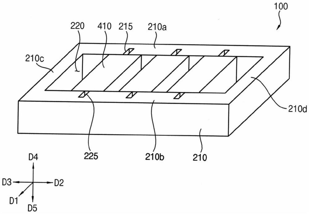
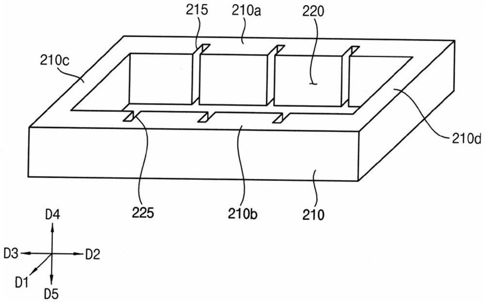
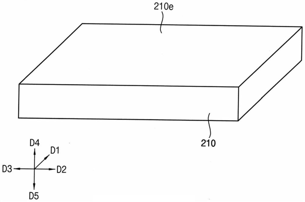
[0067] figure 1 is a perspective view showing a crucible according to an exemplary embodiment of the present invention, figure 2 as well as image 3 is shown included in figure 1 A perspective view of the main body of the crucible. Figure 4 is shown included in figure 1 A perspective view of a metal part of a crucible formed with a deposited substance, Figure 5 is shown included in figure 1 Perspective view of the metal parts of the crucible. Figure 6 is showing Figure 4 Side view of a metal part formed with deposited species. For example, image 3 It is a perspective view for explaining the bottom surface of the...


PUM


Abstract

The present invention relates to a crucible, which may include: a main body storing a deposited substance, and including a first tank; and a first metal member fastened to the first groove, extending in a first direction, and fixing the deposited substance. Accordingly, the crucible comprises the metal part for fixing the deposition substance in the solid state, so that the deposition substance can be completely melted, and the temperature rise time of the deposition substance can be relatively shortened.

Description

technical field [0001] The present invention relates to a crucible and a method for depositing substances using the crucible. In more detail, the present invention relates to a crucible using a solid deposition substance and a method of depositing a solid deposition substance using the crucible. Background technique [0002] A flat panel display device is used as a display device replacing a cathode ray tube display device due to characteristics such as light weight and thin profile. Representative examples of such flat panel display devices include liquid crystal display devices and organic light emitting display devices. [0003] In a method of forming constituent elements included in such a display device, an organic light-emitting layer, an organic insulating layer, and the like may be formed using a thermal vacuum deposition process. For example, after storing the deposited material in the crucible, the crucible may be heated to melt the deposited material (eg, conver...

Claims


Application Information

Patent Timeline
Patent Type & Authority Applications(China)
IPC IPC(8): C23C14/24
CPCC23C14/243H10K71/164H10K71/00
Inventor 郑真洙
Owner SAMSUNG DISPLAY CO LTD
Why Eureka
Try Eureka