Double-layer drum reinforced rotor structure of gas compressor of gas turbine

A gas turbine and rotor structure technology, applied in the direction of machines/engines, liquid fuel engines, mechanical equipment, etc., can solve problems affecting the stability and reliability of the rotor structure, achieve the effects of improving rigidity, preventing severe vibration, and prolonging service life

Active Publication Date: 2022-01-14
成都中科翼能科技有限公司
View PDF22 Cites 3 Cited by
  • Summary
  • Abstract
  • Description
  • Claims
  • Application Information

AI Technical Summary

Problems solved by technology

[0008] In order to solve the problem that the stress of the rotor structure of the compressor in the prior art affects the stability and reliability of the rotor structure when it is rotating at high speed, this solution provides a double-drum reinforced rotor for the gas turbine compressor structure

Method used


Image

  • Double-layer drum reinforced rotor structure of gas compressor of gas turbine
  • Double-layer drum reinforced rotor structure of gas compressor of gas turbine
  • Double-layer drum reinforced rotor structure of gas compressor of gas turbine

Examples


Embodiment 1

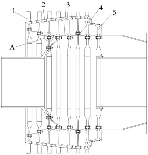
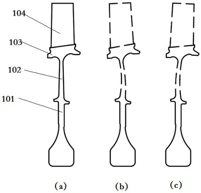
[0032] Such as Figure 1 to Figure 4 As shown, in view of the above problems, this embodiment designs a double-drum reinforced rotor structure of a gas turbine compressor. By slightly deforming the web 102 of the control impeller 1, the web 102 is in a non-working state. It has a certain prestress, and in the working state, the prestress is used to balance or eliminate the new stress generated when the rotor rotates at high speed.

[0033] The rotor structure in this scheme is a double-layer frame structure formed by the working impeller 1, the outer drum 2, the inner drum 3 and the sealing grate disc 5. Wherein, the working impeller 1 includes a first-stage working impeller, a second-stage working impeller, a third-stage working impeller, a fourth-stage working impeller, a fifth-stage working impeller, a sixth-stage working impeller, and a seventh-stage working impeller; The axial direction is arranged in sequence from front to back, wherein the first-stage working impeller ...

Embodiment 2

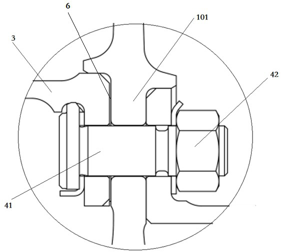
[0040] On the basis of the rotor structure in Example 1, the micro-deformation of the web 102 of the working impeller 1 at each stage is caused by bolts tightening the working impeller 1 and the previous inner drum 3 connected to it, and eliminating the gap between the two. The reserved axial clearance 6 is realized.

[0041] Before using bolts to tighten the web 102 of the corresponding working impeller 1, the axial gap 6 between the working impeller 1 and the inner drum 3 of the preceding stage can be defined as the first gap; Behind the web 102, the axial gap 6 between the working impeller 1 and the inner drum 3 of the previous stage can be defined as the second gap; after the bolt tightens the web 102, the working impeller 1 and its The internal drums 3 of the previous stage can be one of clearance fit, transition fit and interference fit. When the working impeller 1 and the inner drum 3 are in transition fit and interference fit, the micro-deformation of the web 102 of t...


PUM


Abstract

The invention belongs to the technical field of gas compressor rotors of gas turbines, and particularly relates to a double-layer drum reinforced rotor structure of a gas compressor of a gas turbine. An inner drum and an outer drum are arranged between adjacent stages of working impellers; and the inner drum can tension the working impellers so as to balance the stress of a web in the axial direction. According to the reinforced rotor structure in the scheme, the original shape change amount of a hybrid rotor is small while the performance of structural strength, rigidity, stability and the like is reinforced, rotor parts and connection of the rotor parts are stable and reliable, and the rigidity of the rotor structure can be remarkably improved; due to the fact that the structure of the inner drum and the outer drum is adopted, the shock resistance of the rotor can be improved, stable operation of the rotor can be guaranteed under the action of impact force of natural wind or impact force transmitted by natural factors such as sea wave jolting through an outer casing, the rotor has higher rigidity and more reasonable stress distribution in the radial direction and the axial direction, and the service life of the rotor structure is prolonged.

Description

technical field [0001] The invention belongs to the technical field of gas turbine compressor rotors, and in particular relates to a double-drum reinforced rotor structure of a gas turbine compressor. Background technique [0002] A gas turbine is an internal combustion power machine that converts the energy of gas into useful work. It is widely used in many fields, such as: in the field of civil power generation or as a power plant in aircraft or large ships. The working process of the gas turbine is: the compressor continuously inhales air from the atmosphere and compresses the air; the compressed air enters the combustion chamber, mixes with the gas injected into the combustion chamber and burns, and then becomes high-temperature gas, and then the high-temperature gas flows into the combustion chamber It expands to the gas turbine to do work, and uses high-temperature gas to drive the turbine to rotate with the compressor; the gas turbine is a device with good cleanliness...

Claims


Application Information

Patent Timeline
Patent Type & Authority Applications(China)
IPC IPC(8): F04D29/26F04D29/60
CPCF04D29/26F04D29/601
Inventor 王鸣王蕊闪颂武梁豪豪杨万金陈涛富健强
Owner 成都中科翼能科技有限公司
Why Eureka
Try Eureka