Magnetic isolation electronic switch driving circuit and control method

A technology for electronic switches and driving circuits, applied in electronic switches, circuits, electrical components, etc., can solve the problem of inability to adapt to low frequency or even limit duty cycle, and achieve reliable opening and fast switching.

Pending Publication Date: 2022-01-14
SHENZHEN YINGFEIYUAN TECH CO LTD
View PDF0 Cites 1 Cited by
  • Summary
  • Abstract
  • Description
  • Claims
  • Application Information

AI Technical Summary

Problems solved by technology

[0008] The main purpose of the present invention is to propose a magnetically isolated electronic switch drive circuit and control method, on the basis of ensuring that the electronic switch realizes fast switching (fast turn-off, fast turn-on), it also solves the inability to adapt to the problem mentioned in the background technology. Technical issues at low frequencies and even extreme duty cycles

Method used


Image

  • Magnetic isolation electronic switch driving circuit and control method
  • Magnetic isolation electronic switch driving circuit and control method
  • Magnetic isolation electronic switch driving circuit and control method

Examples


Embodiment 1

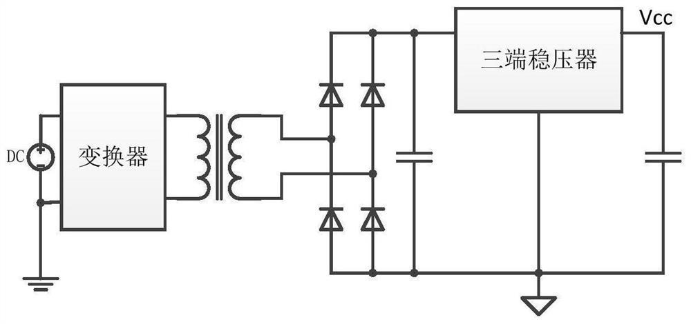
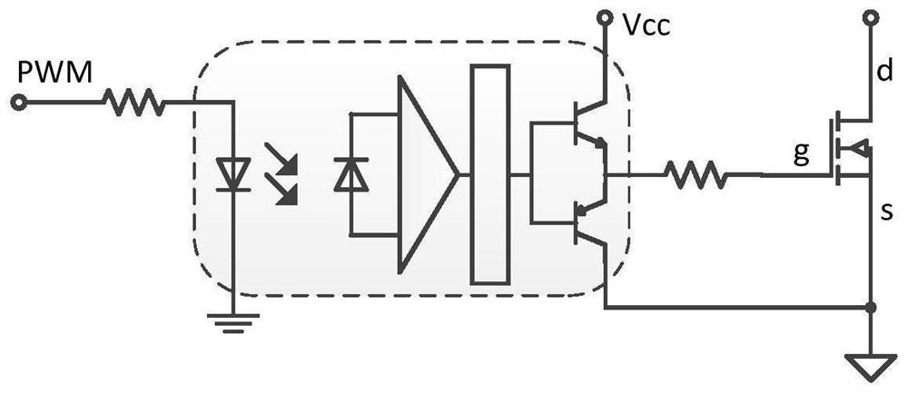
[0048] Such as Figure 5 , Figure 6 As shown, a magnetic isolation electronic switch drive circuit provided by the present invention includes a secondary rectification and filtering module 20, a fast discharge module 30, a voltage stabilizing drive module 40 and an isolation module 70; the secondary rectification and filtering module 20 has a first Input terminals 1, 2 and a first output terminal, the first output terminal has a first output positive terminal 3 and a first output negative terminal 4; the first input terminals 1, 2 are connected to the primary conversion module 10 through a transformer T1, the first output terminal A first filter is arranged between an output positive terminal 3 and a first output negative terminal 4; the fast discharge module 30 has a second input terminal 5 and a second output terminal 6, 7, and the second input terminal 5 and a second output terminal A switching device is arranged between the terminals 6 and 7; the voltage stabilizing driv...

Embodiment 2

[0059] Figure 7 A schematic circuit connection diagram of Embodiment 2 in the magnetic isolation electronic switch drive circuit of the present invention is shown. The circuit structure of Embodiment 2 is based on Embodiment 1, and specifically defines the secondary side rectification and filtering module, which may be a full-wave rectification module or a full-bridge rectification module.

[0060] In Embodiment 2, when the secondary side rectification and filtering module is a full-wave rectification module, the full-wave rectification module includes a first diode D1 and a second diode D2, and the anode of the first diode D1 is connected to the transformer One output end of the first winding on the secondary side of T1 is connected, the anode of the second diode D2 is connected to an output end of the second winding on the secondary side of the transformer T1, and the cathode of the first diode D1 is connected to the second diode D2 at the same time The cathode of the firs...

Embodiment 3

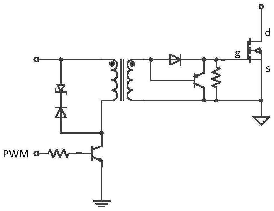
[0063] Figure 8 A schematic circuit connection diagram of Embodiment 3 in the magnetic isolation electronic switch drive circuit of the present invention is shown. The circuit structure of embodiment 3 is improved on the basis of embodiment 1. The difference between embodiment 3 and embodiment 1 is that a threshold accelerated discharge sub-module 50 is arranged in the secondary side rectification and filtering module, and other circuit structures are all the same as those of embodiment 1. 1 is the same, so it will not be repeated here. The threshold accelerated discharge sub-module includes a third triode Q3, a second triode Q2, a fifth resistor R5, a sixth resistor R6, a seventh resistor R7 and a first regulator D6. The third triode Q3 The collector of the collector is connected to one end of the seventh resistor R7, the other end of the seventh resistor R7 is connected to the first output positive terminal 3 with the fifth resistor R5 and the sixth resistor R6 at the same...


PUM


Abstract

The invention discloses a magnetic isolation electronic switch driving circuit and a control method, the magnetic isolation electronic switch driving circuit comprises a secondary side rectification filtering module, a first input end of the secondary side rectification filtering module is connected with a primary side conversion module through a transformer, and a first filter is arranged between a first output positive end and a first output negative end; a switching device is arranged between a second input end and a second output end of the rapid discharging module, a second filter is arranged between a third input end and a third output end of the voltage stabilization driving module, and the third output end is connected with an electronic switch; the fourth input end of the isolation module is connected with the second input end of the rapid discharging module and the secondary side rectification filtering module at the same time, and the fourth output end of the isolation module is connected with the second output end of the rapid discharging module and the voltage stabilization driving module at the same time. According to the invention, on the basis of ensuring that the electronic switch realizes quick switching (quick switching-off and quick switching-on), the limit duty ratio 0 (the electronic switch is normally closed) and 100% (the electronic switch is normally open) control can be realized, so that the magnetic isolation electronic switch driving circuit can be applied to more use scenes.

Description

technical field [0001] The invention relates to the technical field of electronic switches, in particular to a magnetic isolation electronic switch drive circuit and a control method. Background technique [0002] In the field of industrial applications, electronic switches are operating units that use electronic circuits and power electronic devices to realize circuit on-off, usually including at least one controllable electronic drive device, such as thyristors, transistors, field effect transistors, thyristors, relays, etc. . Electronic switches have been widely used in the industrial field due to their fast switching action and small delay time; 300-1000V), therefore, there are usually transformer winding switching in these charging power sources, or series-parallel switching of internal output units. To be done. The on-off of the electronic switch usually needs a corresponding drive circuit to realize. Due to the electrical isolation or safety requirements of the app...

Claims


Application Information

Patent Timeline
Patent Type & Authority Applications(China)
IPC IPC(8): H03K17/041H03K17/0412H03K17/687H03K17/689H03K17/691H02M7/04H02M1/14
CPCH03K17/041H03K17/04106H03K17/04123H03K17/687H03K17/689H03K17/691H02M7/04H02M1/14
Inventor 余时强李广张强李坡
Owner SHENZHEN YINGFEIYUAN TECH CO LTD
Why Eureka
Try Eureka