Differential pressure driving type four-way valve and refrigerating system

A differential pressure drive, four-way valve technology, applied in multi-way valves, valve details, valve devices, etc., can solve the problems of reduced service life and reliability, waste of electric energy of solenoid valves, etc., to avoid waste, save electric energy, and simplify Effects of Design and Control Sophistication

Pending Publication Date: 2022-01-18
GREE ELECTRIC APPLIANCES INC
View PDF0 Cites 6 Cited by
  • Summary
  • Abstract
  • Description
  • Claims
  • Application Information

AI Technical Summary

Problems solved by technology

[0008] Therefore, the technical problem to be solved by the present invention is to overcome the defects of the long-term power-on operation of the solenoid valve in the dual-mode refrigerating system of the fluorine pump heat pipe in the prior art, resulting in waste of electric energy, resulting in reduced service life and reliability, thereby providing a Differential pressure actuated four-way valve and refrigeration system

Method used


Image

  • Differential pressure driving type four-way valve and refrigerating system
  • Differential pressure driving type four-way valve and refrigerating system
  • Differential pressure driving type four-way valve and refrigerating system

Examples


Embodiment 1

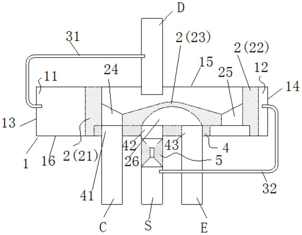
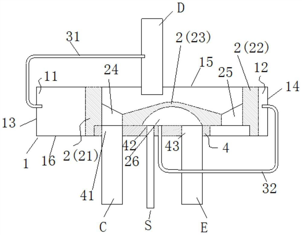
[0033] Example 1, such as Figure 1-2 As shown, the present invention provides a differential pressure driven four-way valve, which includes:

[0034]Valve body 1, sliding body 2, D pipe D, C pipe C, S pipe S, E pipe E, first communicating pipe 31 and second communicating pipe 32, the sliding body 2 is arranged in the valve body 1 and Can slide in the valve body 1, the D pipe D, the C pipe C, the S pipe S and the E pipe E communicate with the inside of the valve body 1 respectively, and the valve body 1 includes The piston chamber A11 on one side of the reciprocating movement of the slider 2 and the piston chamber B12 on the other side of the reciprocating movement, one end of the first communication pipe 31 communicates with the D pipe D, and the other end communicates with the piston chamber A11 communicates to introduce pressure from the D pipe D into the piston chamber A11, one end of the second communication pipe 32 communicates with the S pipe S, and the other end commu...

Embodiment 2

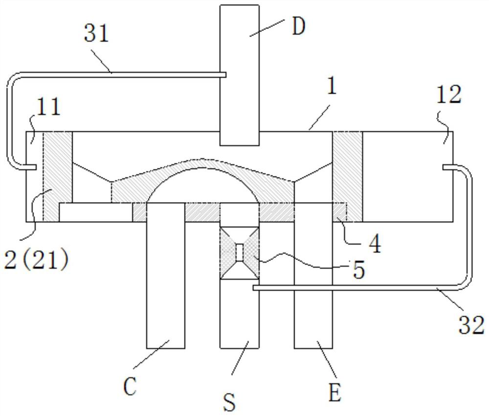
[0056] Example 2, such as Figure 3-4 , in some embodiments, the entire section of the S pipe S is a throttle pipe structure, which is fixedly connected with the valve body 1 . See attached for alternative examples image 3 And attached Figure 4 , with attached figure 1 And attached figure 2 The difference is that the pipe where the S port is located is changed to a throttle tube or a capillary tube. At the same time, the capillary tube B and the S tube are no longer directly connected. The tube port of the capillary tube B is directly connected to the valve body and welded firmly. The process is the same. Other structural design and accessories of four-way valve figure 1 And attached figure 2 same.

[0057] The present invention also provides a refrigeration system (preferably a dual-mode refrigeration system), which includes the differential pressure driven four-way valve described in any one of the preceding items. When working, under one mode, tube D has high pr...


PUM


Abstract

The invention provides a differential pressure driving type four-way valve and a refrigerating system. The differential pressure driving type four-way valve comprises a valve body, a sliding body, a pipe D, a pipe C, a pipe S, a pipe E, a first communicating pipe and a second communicating pipe, wherein one end of the first communicating pipe is communicated with the pipe D, and the other end of the first communicating pipe is communicated with a piston chamber A to introduce pressure into the piston chamber A from the pipe D; one end of the second communicating pipe is communicated with the pipe S, and the other end of the second communicating pipe is communicated with a piston chamber B to introduce pressure into the piston chamber B from the pipe S; and the sliding body can be controlled to slide according to the pressure of the working medium in the piston chamber A and the pressure of the working medium in the piston chamber B. The four-way valve does not need to be driven by an electromagnetic coil, waste of electric energy is avoided, the electric energy is saved, and the service life and reliability of the control valve and the refrigerating system are improved; and the design of the controller and the complexity of control are simplified.

Description

technical field [0001] The invention relates to the technical field of refrigeration, in particular to a differential pressure driven four-way valve and a refrigeration system. Background technique [0002] With the extensive application of 4G and the gradual popularization of 5G, the heat generated by various data processing equipment is increasing, and the cooling capacity and energy saving requirements of air conditioning equipment in data centers are also getting higher and higher. [0003] Using outdoor natural cooling sources in transitional seasons and cold winters to cool data centers can greatly reduce the operating costs of air-conditioning equipment. Fluorine pump air-conditioning is commonly used, and its energy efficiency ratio is very high during normal operation. When the outdoor temperature is low, the fluorine pump mode is enabled, and the compressor is stopped to use the fluorine pump to drive the refrigerant to realize the cooling operation of the heat pip...

Claims


Application Information

Patent Timeline
Patent Type & Authority Applications(China)
IPC IPC(8): F16K11/065F16K31/122F16K31/363F16K27/04F16K47/08F25B41/20
CPCF16K11/0655F16K31/1225F16K31/1223F16K31/363F16K27/044F16K47/08F25B41/20
Inventor 林海佳黄玉优赵材波康建李蓉
Owner GREE ELECTRIC APPLIANCES INC
Why Eureka
Try Eureka