Optical detection unit, optical detection device, and electronic equipment

An optical detection and optical chip technology, applied in measurement devices, optical components, optical radiation measurement, etc., can solve the problems of poor user experience, affecting the performance of ambient light sensors, low screen ratio, etc., and achieve good light intensity sensing and accurate. effect of light intensity, good optical imaging effect and light intensity sensing accuracy

Pending Publication Date: 2022-01-18
ONEPLUS TECH SHENZHEN
View PDF4 Cites 0 Cited by
  • Summary
  • Abstract
  • Description
  • Claims
  • Application Information

AI Technical Summary

Problems solved by technology

The area of ​​the display area is reduced due to the need to reserve a non-display area for the front camera and the ambient light sensor to receive the light beam
The non-display area cannot be used for display, resulting in a low screen-to-body ratio of the electronic device and poor visual aesthetics
In addition, some electronic products place the ambient light sensor under the display to obtain a high screen-to-body ratio. Due to the impact of the display on the ambient light transmittance, this will affect the performance of the ambient light sensor and the user experience is poor.

Method used


Image

  • Optical detection unit, optical detection device, and electronic equipment
  • Optical detection unit, optical detection device, and electronic equipment
  • Optical detection unit, optical detection device, and electronic equipment

Examples


Embodiment Construction

[0027] In order to make the object, technical solution and advantages of the present invention clearer, the present invention will be further described in detail below in conjunction with the accompanying drawings and embodiments. In the case of no conflict, the following embodiments and technical features thereof can be combined with each other. It should be understood that the specific embodiments described here are only used to explain the present invention, not to limit the present invention.

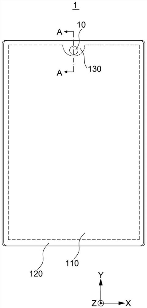
[0028] see figure 1 , is a schematic front view of an electronic device 1 according to the present application. The front of the electronic device 1 has a display area 110 and a non-display area 120 located around or at the edge of the display area 110 . The display area 110 can be used to display information including but not limited to text, images, colors and the like. The non-display area 120 has a notch 130 . The optical detection device 10 is arranged at the notch 130 . Th...


PUM


Abstract

The invention discloses an optical detection unit which is used for receiving a detection light beam penetrating through a lens assembly and converting the received detection light beam into an electric signal. The electric signal is used for generating an image or sensing light intensity, and the optical detection unit comprises a first optical chip which is used for receiving the detection light beam and converting the detection light beam into an electric signal and generating a corresponding image, and a second optical chip which is used for receiving the detection light beam and converting the detection light beam into an electric signal so as to sense the light intensity of the detection light beam. The invention further discloses an optical detection device and electronic equipment.

Description

technical field [0001] The present application relates to the field of optoelectronics, in particular, to an optical detection unit, an optical detection device and electronic equipment. Background technique [0002] With the advancement of technology and the improvement of people's living standards, users require more functions and stylish appearances for electronic products such as mobile phones and tablet computers. At present, the development trend of electronic products such as mobile phones is to have a high screen-to-body ratio, such as a full screen with a screen-to-body ratio of more than 90%. However, when current front-facing cameras, ambient light sensors and other devices are applied to mobile phones, they will occupy the display area of ​​the screen, resulting in a decrease in screen-to-body ratio. For example, in order to be able to detect the intensity of ambient light or receive ambient light for imaging, it is necessary to open a window on the cover glass ...

Claims


Application Information

Patent Timeline
Patent Type & Authority Applications(China)
IPC IPC(8): G01J1/04G02B5/20
CPCG01J1/0437G01J1/0407G02B5/208
Inventor 刘伟黄昌斌刘政肖青武广文苏丹丹王志
Owner ONEPLUS TECH SHENZHEN
Why Eureka
Try Eureka