
Control device for internal combustion engine

A technology for control devices and internal combustion engines, which is applied to other devices, inductive energy storage devices, spark ignition controllers, etc., can solve the problems of reduced energy inside the ignition coil, no longer able to maintain the discharge path, and re-discharge, etc. The effect of wear and ignition failure suppression

Active Publication Date: 2022-01-18
HITACHI ASTEMO LTD
View PDF6 Cites 0 Cited by
  • Summary
  • Abstract
  • Description
  • Claims
  • Application Information

AI Technical Summary

Problems solved by technology

However, in general, since the internal energy of the ignition coil continues to decrease over time from the start of the discharge, the current required to maintain the discharge path cannot be supplied gradually.
[0006] As a result, there is a problem that the discharge path can no longer be maintained during gas combustion, and redischarge is required.

Method used


Image

  • Control device for internal combustion engine
  • Control device for internal combustion engine
  • Control device for internal combustion engine

Examples


no. 1 approach

[0106] [First Embodiment: Circuit of Ignition Coil]

[0107] Next, the circuit 400 including the ignition coil 300 according to the first embodiment of the present invention will be described.

[0108] Figure 8 It is a diagram illustrating a circuit 400 including an ignition coil 300 according to the first embodiment of the present invention. In circuit 400 , ignition coil 300 includes two types of primary coils 310 , 360 wound with a predetermined number of turns, and secondary coil 320 wound with a larger number of turns than primary coils 310 , 360 . Here, when the spark plug 200 is ignited, the electric power from the primary coil 310 is first supplied to the secondary coil 320 , and the electric power from the primary coil 360 is supplied to the secondary coil 320 superimposed on this electric power. Therefore, below, the primary-side coil 310 is referred to as a "main-side coil", and the primary-side coil 360 is referred to as a "sub-primary coil". In addition, the c...

no. 2 approach

[0156] [Second Embodiment: Circuit of Ignition Coil]

[0157] Next, a circuit 400A including the ignition coil 300 according to the second embodiment of the present invention will be described.

[0158] Figure 13 It is a diagram illustrating a circuit 400A including an ignition coil 300 according to the second embodiment of the present invention. In this embodiment, the ignition coil 300 has the same Figure 8 same structure. That is, the ignition coil 300 of the present embodiment also includes two types of primary side coils 310 and 360 (main primary coil 310 and sub primary coil 360 ) each wound with a predetermined number of turns, and a larger number of primary side coils 310 and 360 . The secondary side coil 320 is wound with a number of turns.

[0159] In this embodiment, the circuit 400A differs from the circuit 400 described in the first embodiment in that the current detection unit 370 and the current comparison unit 380 are omitted. In addition, in the present...


PUM


Abstract

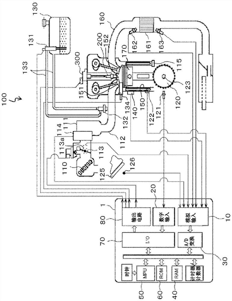
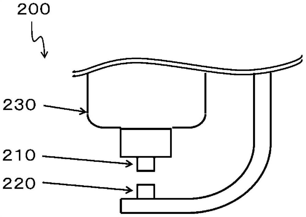
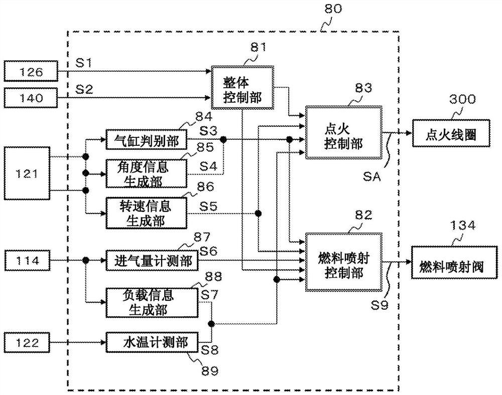
The present invention suppresses electrode wear of a spark plug in an internal combustion engine while suppressing poor ignition of fuel by the spark plug. This control device 1 for an internal combustion engine comprises an ignition control unit that controls the electrification of an ignition coil 300 for providing electric energy to a spark plug 200 that discharges electricity inside a cylinder 150 of the internal combustion engine 100 and ignites the fuel. The ignition control unit controls the electrification of the ignition coil 300 such that first electric energy is emitted from the ignition coil 300 and second electric energy is emitted together with the first electric energy. At this time, the electrification of the ignition coil 300 is controlled such that the emission of the second electric energy is stopped and the electric discharge of the spark plug 200 is stopped at a timing when a change is made on the basis of a gas state near the spark plug 200.

Description

technical field [0001] The present invention relates to a control device for an internal combustion engine. Background technique [0002] In recent years, in order to improve the fuel consumption of vehicles, internal combustion engines have been developed that use a technology that burns an air-fuel mixture leaner than the theoretical air-fuel ratio to operate the internal combustion engine, and a technology that introduces a part of the exhaust gas after combustion and reintakes it. control device. [0003] In such a control device for an internal combustion engine, since the amounts of fuel and air in the combustion chamber deviate from theoretical values, poor ignition of the fuel by the spark plug tends to occur. Therefore, there is a method of increasing the gas flow velocity in the combustion chamber to increase the flow velocity between the electrodes of the spark plug to form a longer discharge path, thereby prolonging the contact length between the discharge path ...

Claims


Application Information

Patent Timeline
Patent Type & Authority Applications(China)
IPC IPC(8): F02P3/00F02P3/05
CPCF02P3/00F02P3/05F02P17/12F02P2017/121F02P9/007F02P3/053Y02T10/40F02P3/0442
Inventor 大畠英一郎
Owner HITACHI ASTEMO LTD
Learn More