internal combustion engine
A technology for internal combustion engines and compressors, applied in the direction of internal combustion piston engines, combustion engines, engine components, etc., can solve problems such as internal combustion engine misfires, achieve the effects of suppressing misfires and improving tolerance
- Summary
- Abstract
- Description
- Claims
- Application Information
AI Technical Summary
Problems solved by technology
Method used
Image
Examples
Embodiment 1
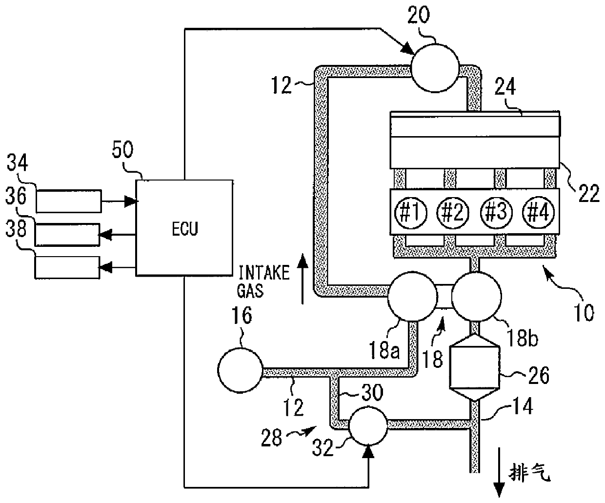
[0047] First, refer to Figure 1 to Figure 6 Example 1 of the present invention will be described.
[0048] [Description of system configuration] figure 1 is a schematic diagram showing the configuration of a system including the internal combustion engine according to Embodiment 1. figure 1 The system shown includes an internal combustion engine 10 . The internal combustion engine 10 is configured as an inline four-cylinder engine installed in a vehicle, and the combustion order of the cylinders is: first cylinder #1, third cylinder #3, fourth cylinder #4, and second cylinder #2, which Same as in normal engine. The intake passage 12 and the exhaust passage 14 communicate with each cylinder (combustion chamber) of the internal combustion engine 10 .
[0049] An air cleaner 16 is installed near the inlet of the intake passage 12 . A compressor 18 a of the turbocharger 18 is arranged downstream of the air filter 16 . The compressor 18 a is driven by the rotation of a turbi...
Embodiment 2
[0070] [Description of system configuration] Next, refer to Figure 7 and Figure 8 Example 2 of the present invention will be described.
[0071] The configuration of the system of Embodiment 2 is basically the same as that of Embodiment 1 described above. However, Embodiment 2 differs from the configuration of Embodiment 1 described above in that internal combustion engine 10 is an inline two-cylinder engine including a first cylinder #1 and a second cylinder #2.
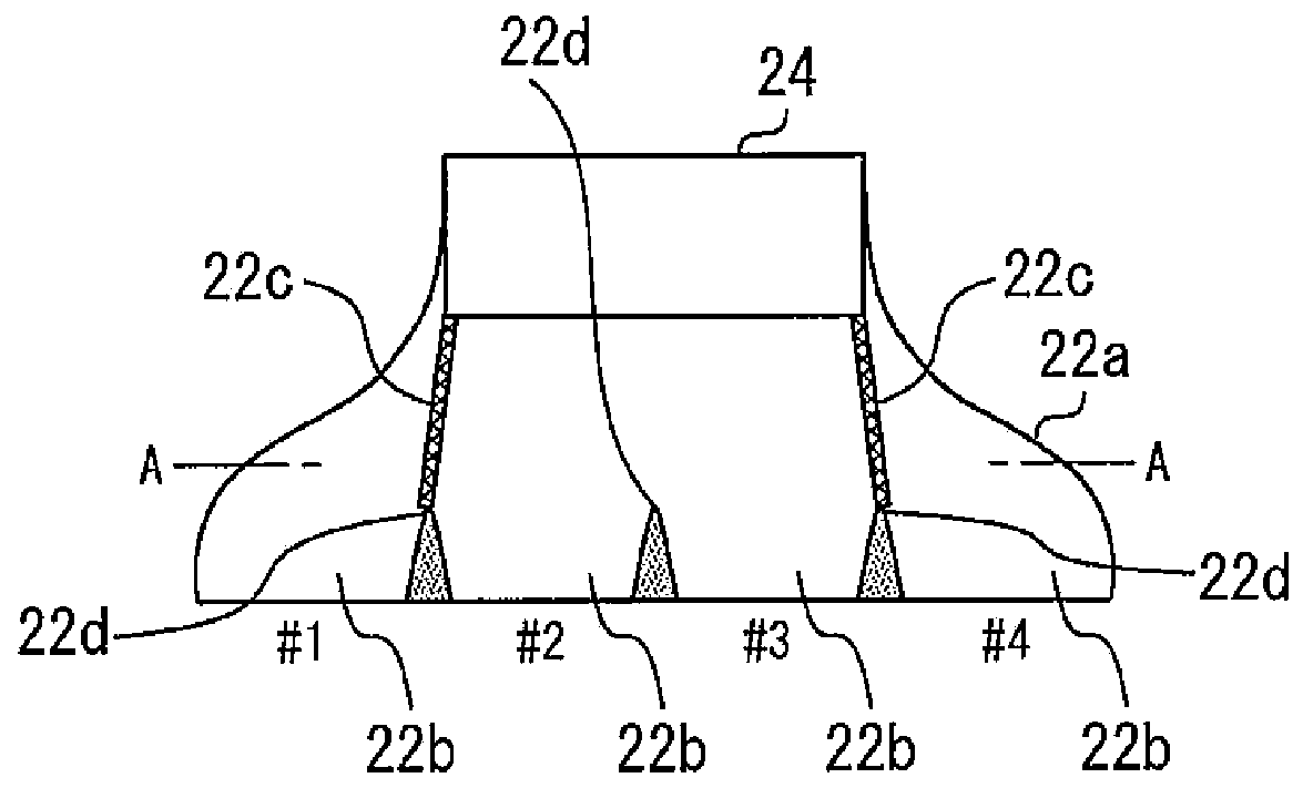
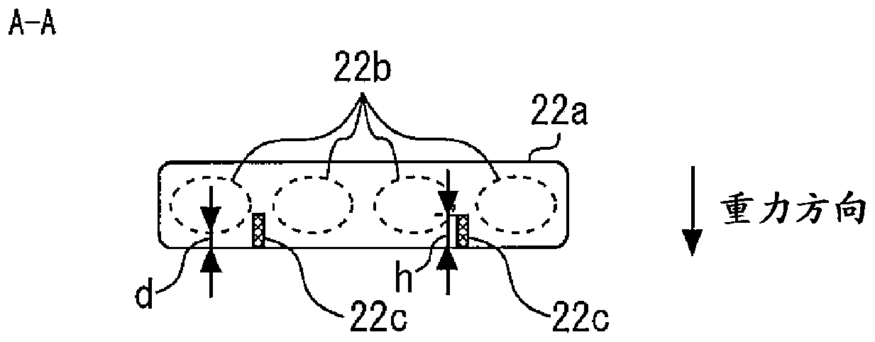
[0072] Figure 7 It is a schematic diagram showing the inside of the intake manifold 22 of the second embodiment. Such as Figure 7 As shown, a guiding device 22c is provided at the bottom of the collective portion 22a. The guide 22c is provided from the vicinity of the outlet portion located on the right side of the intercooler 24 to the branch portion 22d between the first cylinder #1 and the second cylinder #2. Figure 8 is along Figure 7 Cross-sectional view of line A-A in. Such as Figure 8 As shown...
Embodiment 3
[0077] [Description of system configuration] Next, refer to Figure 9 and Figure 10 Embodiment 3 of the present invention will be described.
[0078] The configuration of the system of Embodiment 3 is basically the same as that of Embodiment 1 described above. However, Embodiment 3 differs from the configuration of Embodiment 1 described above in that internal combustion engine 10 is an inline six-cylinder engine including first cylinder #1 to sixth cylinder #6. Note that the combustion order of the internal combustion engine 10 is: the first cylinder #1, the fifth cylinder #5, the third cylinder #3, the sixth cylinder #6, the second cylinder #2, the fourth cylinder #4; or the first cylinder #1, fourth cylinder #4, second cylinder #2, fifth cylinder #5, third cylinder #3, sixth cylinder #6.
[0079] Figure 9 It is a schematic diagram showing the inside of the intake manifold 22 of the third embodiment. Such as Figure 9 As shown, only one guide 22c is provided at the b...
PUM
 Abstract
Description
Claims
Application Information
 - R&D
- Intellectual Property
- Life Sciences
- Materials
- Tech Scout
- Unparalleled Data Quality
- Higher Quality Content
- 60% Fewer Hallucinations
Browse by: Latest US Patents, China's latest patents, Technical Efficacy Thesaurus, Application Domain, Technology Topic, Popular Technical Reports.
© 2025 PatSnap. All rights reserved.Legal|Privacy policy|Modern Slavery Act Transparency Statement|Sitemap|About US| Contact US: help@patsnap.com


