
fuel injection device

A fuel injection device and injector technology, which is applied in the directions of fuel injection device, fuel injection control, charging system, etc., can solve the problems of complicated structure and increased manufacturing cost, and achieve the effect of suppressing misfire and suppressing misfire

Inactive Publication Date: 2017-05-03
SUZUKI MOTOR CORP
View PDF5 Cites 0 Cited by
  • Summary
  • Abstract
  • Description
  • Claims
  • Application Information

AI Technical Summary

Problems solved by technology

[0003] In general, a vehicle equipped with a dual-fuel engine has an injector for injecting gasoline and an injector for injecting CNG for each cylinder formed in the internal combustion engine, so there is a problem that the manufacturing cost increases and the structure becomes complicated.

Method used


Image

  • fuel injection device
  • fuel injection device
  • fuel injection device

Examples


no. 1 Embodiment approach

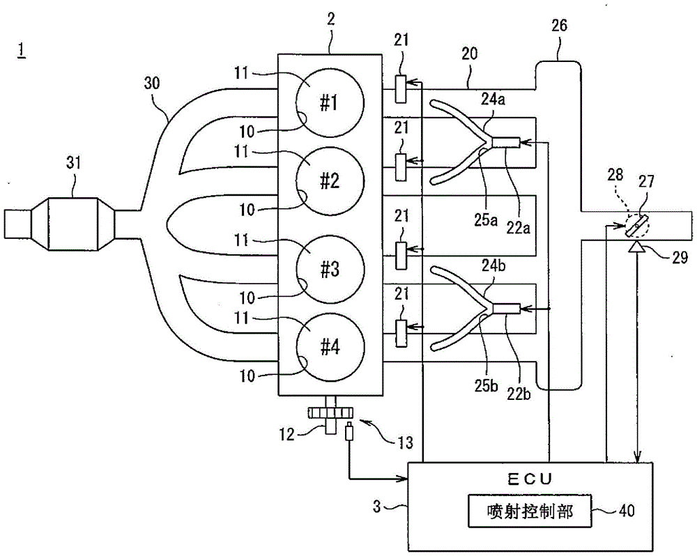
[0037] Such as figure 1 As shown, a vehicle 1 equipped with the fuel injection device according to the first embodiment of the present invention includes an internal combustion engine 2 and an ECU (Electronic Control Unit: Electronic Control Unit) 3 .

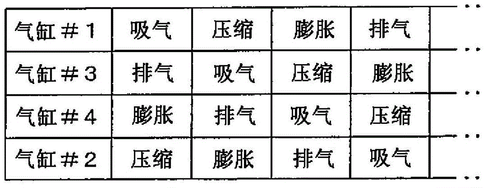
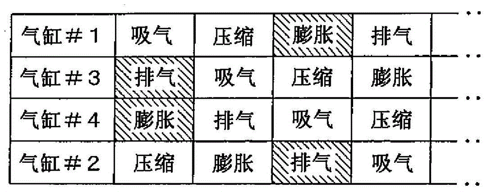
[0038] A plurality of cylindrical cylinders 10 are formed in the engine 2 . Piston 11 is housed in each cylinder 10 so as to be capable of reciprocating movement. Such as figure 2 As shown, the engine 2 is composed of a four-stroke engine. During the two reciprocations of the piston 11 in the cylinder 10, a series of 4 strokes including the intake stroke, compression stroke, expansion stroke and exhaust stroke are performed, and the compression stroke Ignition is performed during the expansion stroke.

[0039] In the present embodiment, the engine 2 is made of an in-line 4-cylinder engine, but in the present invention, the engine 2 can be an in-line 6-cylinder engine, a V-type 6-cylinder engine, a V-type 12-cylinder engine...

no. 2 Embodiment approach

[0077] In this embodiment, differences from the first embodiment of the present invention will be described. In addition, among the components of this embodiment, the same components as those of the first embodiment of the present invention are assigned the same reference numerals, and different points will be described.

[0078] Such as Figure 4 As shown, the injection port of the gaseous fuel injector 22a of this embodiment is connected to a fuel supply pipe 50a. In addition, the injection port of the gas fuel injector 22b is connected to the fuel supply pipe 50b.

[0079] The fuel supply pipe 50a branches downstream of the gas fuel injector 22a to form a fuel supply passage 51a communicating with two of the four cylinders 10 to supply CNG equally to the two cylinders 10 . In the present embodiment, the fuel supply passage 51a communicates with the specific cylinder #1 and the cylinder #4 whose ignition order is second to the cylinder #1.

[0080] That is, the fuel suppl...


PUM


Abstract

A fuel jet device is provided. The fuel jet device can seek low manufacturing cost and simplified structure fully compared with a present fuel jet device. The fuel jet device comprises a fuel supply pipe (24a), a fuel supply pipe (24b) and a jet control section (60). The fuel supply pipe (24a) forms fuel supply channels (25a) communicated with a first cylinder and a second cylinder formed in an engine (2) at a branch of the downstream side of a gas fuel injector (22a) and are used for supplying CNG for the two cylinders equally. The fuel supply pipe (24b) forms fuel supply channels (25b) communicated with a third cylinder and a fourth cylinder formed in the engine (2) at a branch of the downstream side of a gas fuel injector (22b) and are used for supplying CNG for the two cylinders equally. The jet control section (60) controls the gas fuel injector (22a) and the gas fuel injector (22b) to start injection of CNG the special second and third cylinders are in an outstroke.

Description

technical field [0001] The present invention relates to a fuel injection device, and more specifically, to a fuel injection device for an internal combustion engine that uses at least gaseous fuel as a driving fuel. Background technique [0002] As a vehicle equipped with an internal combustion engine that uses at least gaseous fuel as a driving fuel, for example, gasoline as a liquid fuel and compressed natural gas (Compressed Natural Gas, hereinafter referred to as "CNG") as a gaseous fuel are known. A vehicle with a dual-fuel engine whose fuel is used as fuel for driving. [0003] In general, a vehicle equipped with a dual-fuel engine has an injector for injecting gasoline and an injector for injecting CNG for each cylinder formed in the internal combustion engine. Therefore, there are problems in that the manufacturing cost increases and the structure becomes complicated. [0004] As a solution to such a problem, JP 2004-124891 A proposes to supply liquid fuel to a plur...

Claims


Application Information

Patent Timeline
Patent Type & Authority Patents(China)
IPC IPC(8): F02M43/04F02D19/06F02D41/30
CPCF02D19/0615F02D19/0647F02D19/0686F02D41/0002F02D41/0025F02D41/0027F02D41/22F02D41/345F02D2200/1015Y02T10/30Y02T10/40
Inventor 盐浦勇一郎
Owner SUZUKI MOTOR CORP
Learn More