Integrated optimized lifting structure of cookware tray

A lifting structure and material tray technology, which is applied to the structure of cooking utensils, kitchen utensils, household utensils, etc., can solve the problems of unreasonable assembly of components, difficult disassembly and assembly operations, poor stability of the lifting and lowering of the material tray, etc., to simplify the assembly process, The effect of quick disassembly and assembly and low manufacturing cost

Inactive Publication Date: 2022-01-21
佛山市小为电器科技有限公司
View PDF18 Cites 0 Cited by
  • Summary
  • Abstract
  • Description
  • Claims
  • Application Information

AI Technical Summary

Problems solved by technology

[0004] The purpose of the present invention is to provide an integrated and optimized lifting structure of the pan for cooking utensils, so as to overcome the disadvantages of unreasonable assembly between components, difficult disassembly and assembly operation, and poor lifting stability of the pan in the prior art.

Method used


Image

  • Integrated optimized lifting structure of cookware tray
  • Integrated optimized lifting structure of cookware tray
  • Integrated optimized lifting structure of cookware tray

Examples


no. 1 example

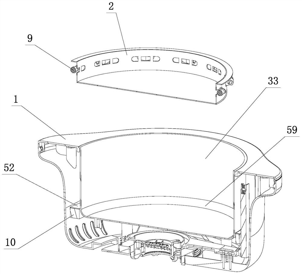
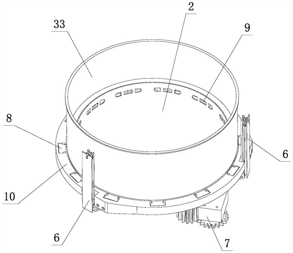
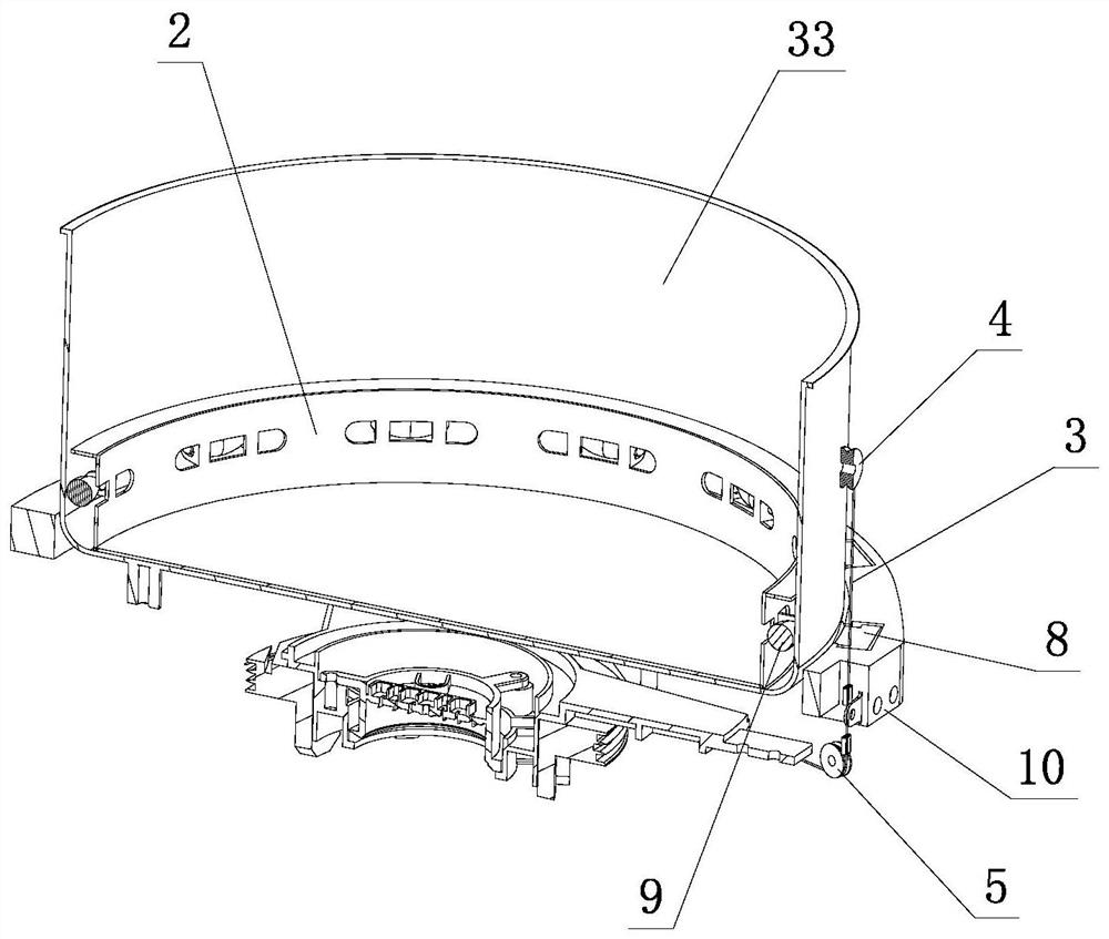
[0044] see Figure 1-Figure 9 , the integrated and optimized lifting structure of the pot material tray includes a pot body 1, an inner container 33 is arranged in the pot body 1, a material tray 2 is arranged in the inner container 33, and a plurality of rolling parts 9 are arranged in an array on the periphery of the material tray 2; The outside of the inner tank 33 is provided with a lifter 10, and on the lifter 10, there are several magnetic bodies 8 that are magnetically matched with the rolling member 9 or the material tray 2; , and when lifting up and down, the magnetic attraction force of the magnetic body 8 drives the material tray 2 up and down in the liner 33.

[0045] Utilizing the magnetic force generated by the magnetic body 8, the lifting member 10 can drive the material tray 2 to move up and down synchronously in the liner 33 when moving up and down, so as to complete the solid-liquid separation in the food.

[0046] The space between the magnetic body 8 and t...

no. 2 example

[0080] see Figure 10-Figure 15 , the integrated and optimized lifting structure of the pot tray is different from the first embodiment in that: there are several holes at the bottom of the tray 2, and several shrapnels 60 and adapters 61 are arranged on the outside; Several shrapnels 60 are elastically arranged on the outside of the tray 2 respectively, several rolling elements 9 are respectively rolled and arranged on the several shrapnels 60, and several adapter pieces 61 are respectively located on the outside of the rolling elements 9 and are respectively positioned on the tray 2 or On several shrapnels 60; said several rolling parts 9 are rolled and arranged on several shrapnels 60 through several adapters 61 respectively, and when the material tray 2 is lifted up and down, the shrapnels 60 can be adaptively elastically moved on the material respectively. Disk 2 outside.

[0081] Utilizing the elastic effect of the shrapnel 60, the rolling member 9 can adapt to the elas...

no. 3 example

[0092] Such as Figure 16 As shown, similar to the second embodiment, the difference is that the outer side of the tray 2 is integrally punched to form a groove 65, the opening 63 is arranged on the groove 65, and the grooves 65 on both sides of the opening 63 are provided with left and right When assembling the crimping part 90, the shrapnel 60 is arranged in the groove 65, and the side parts of the two ends of the shrapnel 60 are provided with assembly holes 91 that cooperate with the left and right crimping parts 90, so that the boss and the assembling hole 91 form a positioning fit, and then The left and right positioning parts 64 are welded at the corresponding positions of the left and right crimping parts 90 to limit the position of the elastic piece 60; the function of the groove 65 is to facilitate the assembly of the elastic piece 60, so that the elastic piece 60 has room for adjustment during assembly.


PUM


Abstract

The invention relates to an integrated optimized lifting structure of a cookware tray. The integrated optimized lifting structure comprises a pot body, an inner container is arranged in the pot body, a material tray is arranged in the inner container, and a plurality of rolling pieces are arranged on the periphery of the material tray in an array mode; a lifting piece is arranged on the outer side of the inner container, and a plurality of magnetic bodies matched with the rolling pieces or the material tray in a magnetic mode are arrayed on the lifting piece. The lifting piece lifts up and down on the outer side of the inner container in a suspension manner, and drives the material tray to lift up and down in the inner container through the magnetic attraction acting force of the magnetic bodies during lifting up and down; the magnetic bodies and the rolling pieces can move in a self-adaptive mode when the material tray ascends and descends, and a demagnetizing area is further arranged between the magnetic bodies and the rolling pieces. When the material tray is lifted up and down to a certain position, the magnetic attraction acting force generated by the magnetic bodies is separated and / or reduced through the demagnetizing area, and the material tray can be detached and taken out from the inner container; a material tray positioning part is arranged in the inner container; the material tray is limited on the material tray positioning part after ascending and descending to a certain position; and when the material tray is limited on the material tray positioning part, a height difference is formed between the lifting piece and the material tray.

Description

technical field [0001] The invention relates to an integrated and optimized lifting structure of a pan for cooking utensils. Background technique [0002] As a kind of ready-to-eat catering and food, hot pot is deeply loved by food lovers. In traditional hot pot meals, there is a phenomenon that the dishes are cooked in the pot and people can't see the specific location of the dishes. They can only use chopsticks or spoons to scoop the dishes out of the soup. Not only is it inconvenient to operate, The meal time is long, and some food has not been fished out for a long time, or is smashed by a spoon and cannot be picked up, resulting in the loss of its nutrition, and it will also cause diners to often fish out dishes or bottom materials by mistake. [0003] Relevant technical personnel make improvement for this reason, as publication number: CN101904684B, name: In a kind of magnetic control type cooking variable electric heating pot, it adopts the main structure such as scr...

Claims


Application Information

Patent Timeline
Patent Type & Authority Applications(China)
IPC IPC(8): A47J27/00A47J36/16
CPCA47J27/002A47J36/16
Inventor 王成斌莫奕田简炳根黎伟文陈土炎
Owner 佛山市小为电器科技有限公司
Why Eureka
Try Eureka