
Ultrasonic imaging device

A camera device and ultrasonic technology, which is applied in the directions of acoustic wave diagnosis, infrasonic wave diagnosis, ultrasonic/sonic wave/infrasonic wave diagnosis, etc., can solve the problems of frame rate reduction, cost increase, signal processing cost increase, etc., and achieve high resolution Effect

Pending Publication Date: 2022-01-21
HITACHI HEALTHCARE MFG LTD
View PDF11 Cites 0 Cited by
  • Summary
  • Abstract
  • Description
  • Claims
  • Application Information

AI Technical Summary

Problems solved by technology

If the distance between dummy elements is reduced to avoid grating lobes, the interval between transmit focus and receive focus will be narrowed, which will lead to a decrease in frame rate and an increase in signal processing costs, etc.
In addition, the number of dummy elements required to maintain the resolution increases, leading to an increase in cost

Method used


Image

  • Ultrasonic imaging device
  • Ultrasonic imaging device
  • Ultrasonic imaging device

Examples


no. 1 Embodiment approach 》

[0051]

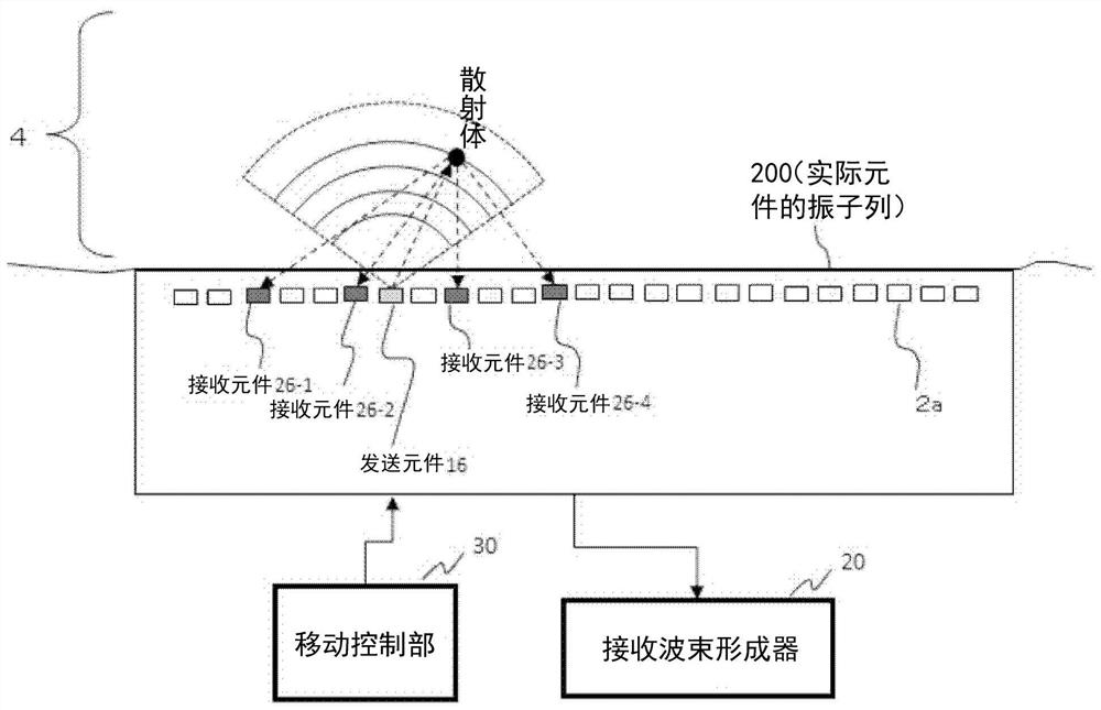
[0052] use figure 1 The outline of the ultrasonic imaging device according to the first embodiment will be described below.

[0053] Such as figure 1 As shown, the ultrasonic imaging device of the first embodiment includes: the transmitting element 16, which transmits ultrasonic waves to the subject 4; echoes of ultrasonic waves generated in the object 4 ; the movement control unit 30 ; and the reception beamformer 20 .

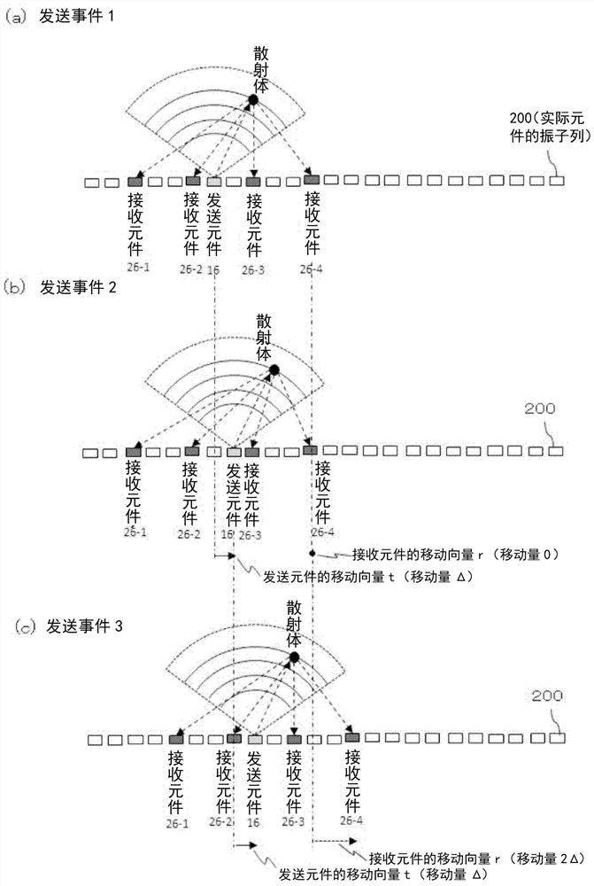
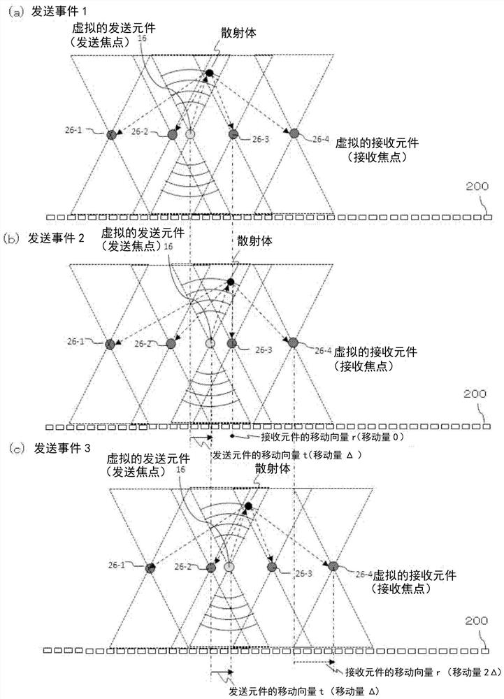
[0054] The sending element 16 and the plurality of receiving elements 26-1 to 26-4 mentioned here include figure 2 In addition to the actual element (vibrator 2a) as in (a) to (c), it also includes image 3 (a) to (c) are cases of virtual elements (eg, elements assumed to be at the positions of the transmission focus and the reception focus in the SASB method as described in Non-Patent Document 1).

[0055] The movement control unit 30 sets the positions of the transmitting element 16 and the receiving elements 26-1 to 26-4 in the alignment d...

no. 2 Embodiment approach 》

[0129] use Figure 12 An ultrasonic imaging device according to a second embodiment will be described. The ultrasonic imaging device of the second embodiment differs from the first embodiment in that the first reception beamformer 202 is mounted on the probe 2 .

[0130] The rest of the structure is the same as that of the device of the first embodiment, so description thereof will be omitted.

[0131] The first reception beamformer 202 performs calculations for forming reception line signals by packing the received signals by the SASB method. Since the calculation amount is small, the scale of the required calculation circuit is also small. Therefore, it can be mounted on the probe 2 .

[0132] In addition, since the number of packed reception line signals is the number of reception apertures, it is only necessary for the probe 2 to transmit the number of reception line signals to the main device 1 less than that of the vibrator 2a. Therefore, the amount of data transmitte...


PUM


Abstract

The invention provides an ultrasonic imaging device. The distance between oscillators is enlarged while a grating lobe is suppressed. The device is provided with: a reception beam former that sets a plurality of reception apertures for a row of oscillators that receive echoes transmitted by a primary transmission beam, performs a given process on reception signals from a plurality of oscillators within the plurality of reception apertures to form reception beams, respectively, performs aperture synthesis on a plurality of the reception beams obtained in a plurality of transmissions of the transmission beams; a control unit which, for each transmission of the transmission beams, moves the position of the transmission aperture and the position of the reception aperture in the column direction of the transducer array is provided. The control unit makes the movement vector of the reception aperture along the column direction of the oscillator different relative to the movement vector of the transmission aperture so that the distance between consecutive transmission of the phase center, which is a midpoint between the center of the transmission aperture and the center of the reception aperture, is smaller than when the transmission aperture and the reception aperture move the transmission aperture and the reception aperture with a constant movement vector.

Description

technical field [0001] The present invention relates to an ultrasonic imaging technique for imaging the inside of a subject using ultrasonic waves. Background technique [0002] The so-called ultrasonic imaging technology is a technique for non-invasively imaging the inside of a subject represented by the human body using ultrasonic waves (involuntary sound waves, generally high-frequency sound waves above 20 kHz). [0003] Ultrasonic imaging is performed by a technique of forming a transmission beam and a reception beam called beamforming. [0004] Synthetic aperture imaging (Synthetic Aperture) is widely used in ultrasonic beamforming. In typical aperture synthesis imaging, one element (vibrator) in the array for transmitting and receiving ultrasonic waves in the ultrasonic probe is used for transmission, and the reflected signal is received by one or more receiving elements. Transmission and reception are repeated while the positions of the elements are shifted sequenti...

Claims


Application Information

Patent Timeline
Patent Type & Authority Applications(China)
IPC IPC(8): A61B8/00
CPCA61B8/00A61B8/5215
Inventor 广岛美咲栗原浩镰田和明
Owner HITACHI HEALTHCARE MFG LTD
Learn More