Solar power generation device and system

A power generation device and solar energy technology, which is applied in the field of solar panels to achieve the effects of improving lifespan, ensuring high efficiency and good shading effect

Inactive Publication Date: 2022-01-21
重庆嘉肯科技有限公司
View PDF1 Cites 0 Cited by
  • Summary
  • Abstract
  • Description
  • Claims
  • Application Information

AI Technical Summary

Problems solved by technology

[0003] The purpose of the present invention is to at least solve one of the technical problems in the prior art, and provide a solar power generation device, which can solve the problem of ensuring that the solar panel power generation mechanism has good protection performance when it is not in use, especially for snowy weather in the north. The good protection effect of covering snow and rain, improving the service life of solar panel power generation mechanism

Method used


Image

  • Solar power generation device and system
  • Solar power generation device and system
  • Solar power generation device and system

Examples


Embodiment 1

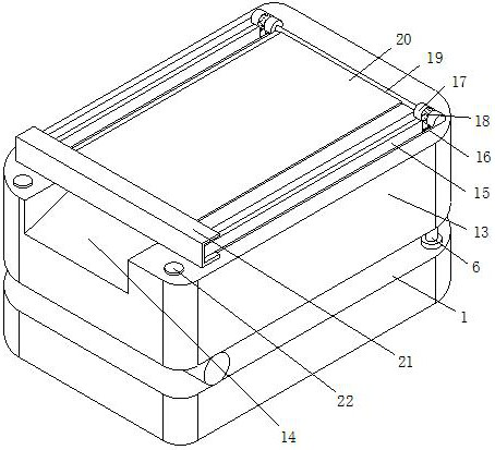
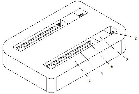
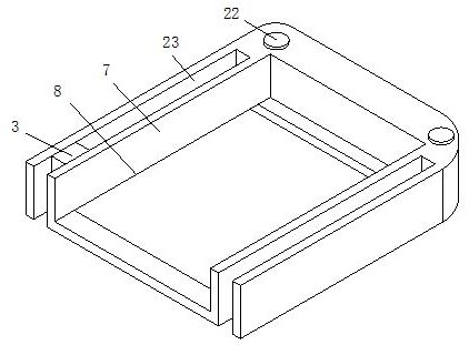
[0036] see Figure 1-7 , the present invention provides a technical solution: a solar power generation device, including a base 1, the inside of the base 1 is slidably connected to an outer plate 3, the left side of the outer plate 3 is rotatably connected to a pulley 4, and the surface of the pulley 4 is rotatably connected to the base 1, the rear side of the outer plate 3 is fixedly connected with the first hydraulic telescopic rod 5, and the rear end of the first hydraulic telescopic rod 5 is fixedly connected with the inside of the base 1, and the inside of the base 1 is fixedly connected with the auxiliary spring 2, and the auxiliary spring The rear end of 2 is in contact with the front side of the outer plate 3, the upper side of the base 1 is fixedly connected with the second hydraulic telescopic rod 6, the upper end of the second hydraulic telescopic rod 6 is rotatably connected with the lower plate 7, and the lower side of the lower plate 7 Rotately connected with the...

Embodiment 2

[0040] see figure 1 , on the basis of Embodiment 1, the protective device includes an inner plate 16, the surface of the inner plate 16 is slidably connected to the inside of the upper groove 15, the upper side of the inner plate 16 is fixedly connected with an outer ring 18, and the lower side of the inner plate 16 slides Connected to the inside of the outer plate 3, the upper side of the inner plate 16 is fixedly connected with an outer ring 18, and the inside of the outer ring 18 is rotatably connected with a rotating rod 17, and the surface of the rotating rod 17 is rotatably connected to the inside of the upper groove 15, and the inner part of the upper groove 15 The shape is concave, the left end of the rotating rod 17 is fixedly connected with the connecting rod 19, the surface of the connecting rod 19 is fixedly connected with the shielding cloth 20, the rear side of the shielding cloth 20 is fixedly connected with the placement plate 21, and the lower side of the place...


PUM


Abstract

The invention discloses a solar power generation device and system, and relates to the technical field of solar panels. The solar power generation device comprises a base, wherein the upper side of the base is fixedly connected with a second hydraulic telescopic rod; the upper end of the second hydraulic telescopic rod is rotationally connected with a lower plate; and the lower side of the lower plate is rotationally connected with the upper side of the base. According to the solar power generation device, an outer plate is driven to move through a first hydraulic telescopic rod, and meanwhile, the outer plate drives an inner plate to move backwards in an upper groove, so that through the rotating effect between a rotating rod and an outer ring, when the inner plate drives the outer ring to slide backwards in the upper groove, the flexibility of shielding and opening of shielding cloth when a solar panel power generation mechanism is used and not used is guaranteed, the solar panel power generation mechanism has a good protection performance when not used, especially the good protection effect of shielding snow and rain on snowy days in the north is achieved, and the service life of the solar panel power generation mechanism is prolonged.

Description

technical field [0001] The invention relates to the technical field of solar panels, in particular to a solar power generation device. Background technique [0002] Compared with the published patent number: 202020906512.5, an environmentally friendly solar power generation device is disclosed. The right side of the rotating shaft is provided with a first gear meshing with the tooth groove, and the upper side of the right lifting column is connected with a second connecting piece. The connecting part is provided with an adjustment component, the right side of the adjustment component is fixedly connected with the mounting frame, the other side of the mounting frame is rotatably connected with the first connecting part, the photovoltaic panel assembly is slidingly connected in the mounting frame, and the left and right sides of the mounting frame are provided with buckles There is a fixing bar on the upper side of the mounting frame, and buckles matching the buckle grooves ar...

Claims


Application Information

Patent Timeline
Patent Type & Authority Applications(China)
IPC IPC(8): B08B17/02H02S20/32H02S30/10F16F15/067
CPCB08B17/02H02S20/32H02S30/10F16F15/067Y02E10/50
Inventor 卢飞虞宝凤
Owner 重庆嘉肯科技有限公司
Why Eureka
Try Eureka