End face punching device for steel beam surface machining

A surface processing and punching device technology, applied in metal processing, metal processing equipment, manufacturing tools, etc., can solve problems such as the deviation of punching positions, the length of I-shaped steel beams, and the impact on the subsequent use of steel beams, so as to avoid The deflection of the position, the effect of reducing the pushing resistance and improving the convenience

Pending Publication Date: 2022-01-21
江苏远大钢结构工程有限公司
View PDF0 Cites 0 Cited by
  • Summary
  • Abstract
  • Description
  • Claims
  • Application Information

AI Technical Summary

Problems solved by technology

[0003] Both ends of the I-shaped steel beam require four or more mounting holes to be punched to meet different installation and assembly requirements. The traditional punching device for steel beam processing is mainly composed of an operating platform and punching equipment. When the I-shaped steel beam is punched, the steel beam is usually placed directly on the operating platform. Since the I-shaped steel beam is relatively long and heavy, after the punching work of one end of the steel beam is completed, it needs to be It is very inconvenient to move and turn to the other end face to continue processing, and because the steel beam body is not limited during the punching work, it is easy to cause the deviation of the punching position, resulting in poor punching quality of the steel beam, Thus affecting the subsequent use of steel beams

Method used


Image

  • End face punching device for steel beam surface machining
  • End face punching device for steel beam surface machining
  • End face punching device for steel beam surface machining

Examples


Embodiment Construction

[0026] The following will clearly and completely describe the technical solutions in the embodiments of the present invention with reference to the accompanying drawings in the embodiments of the present invention. Obviously, the described embodiments are only some, not all, embodiments of the present invention. Based on the embodiments of the present invention, all other embodiments obtained by persons of ordinary skill in the art without making creative efforts belong to the protection scope of the present invention.

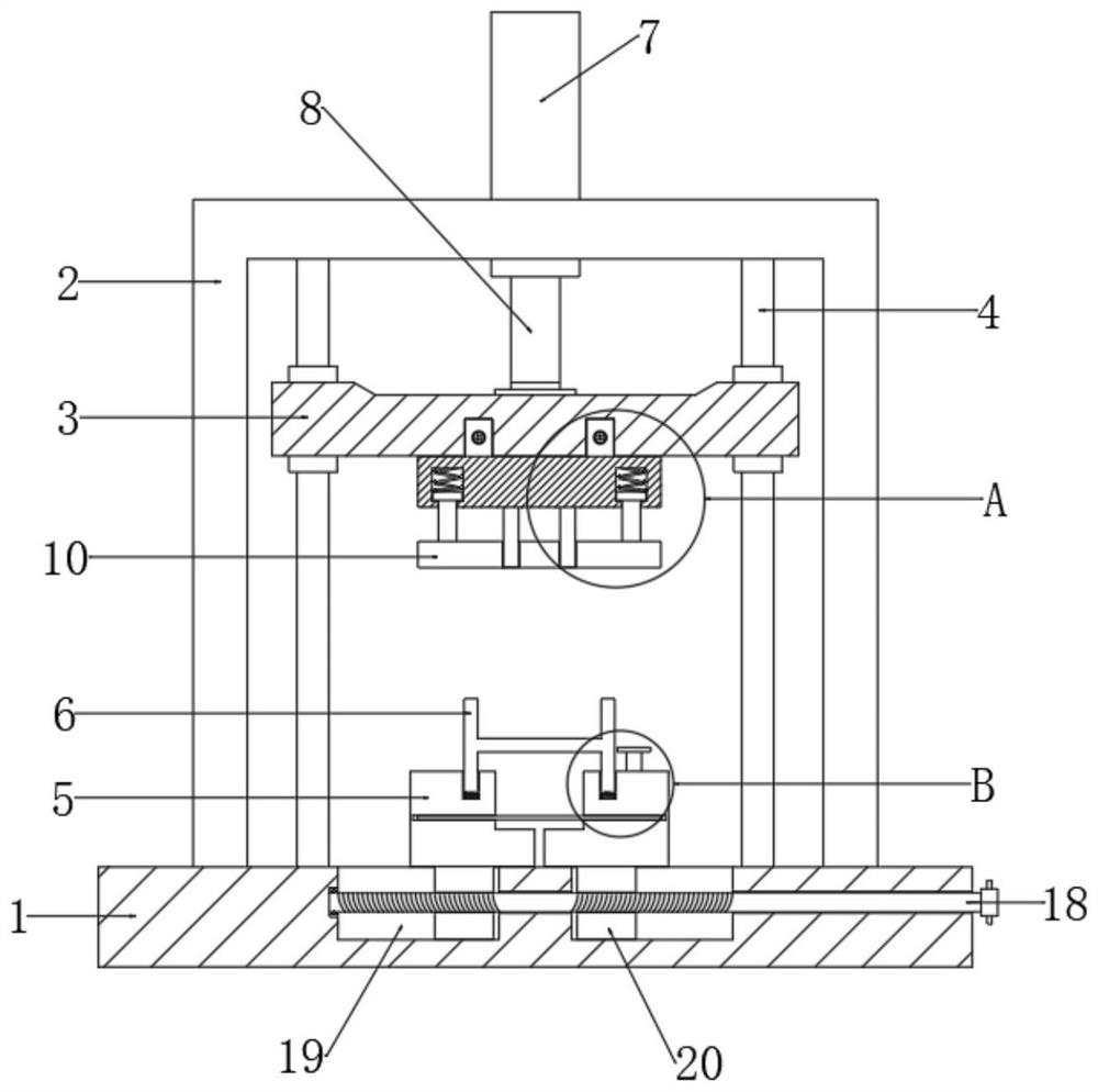
[0027] The invention provides a technical solution, an end face punching device for steel beam surface processing, including an operation table 1, refer to the attached figure 1 And attached Figure 4 , the top of the console 1 is fixedly connected with the gantry 2, the connection between the console 1 and the gantry 2 is realized by welding, and the gantry 2 is vertically fixed on the upper surface of the console 1, and the top of the inner cavity of the gan...


PUM


Abstract

The invention relates to the technical field of steel beam surface machining, and discloses an end face punching device for steel beam surface machining. The end face punching device comprises an operation table, a portal frame is fixedly connected to the top end of the operation table, a cross beam is arranged at the top of an inner cavity of the portal frame, an upper die holder is mounted at the bottom end of the cross beam, and a movable plate is arranged below the upper die holder; and a limiting mechanism is arranged between the upper die holder and the movable plate and comprises two limiting grooves, two reset springs, two limiting blocks and two connecting rods, two placing tables are symmetrically arranged above the operation table, a steel beam body is arranged at the top ends of the two placing tables, and auxiliary mechanisms are arranged between the two placing tables and the steel beam body. According to the end face punching device for steel beam surface machining, through the design of the limiting mechanism and the auxiliary mechanism, position deflection during steel beam body punching is effectively avoided, and the quality of the steel beam body after punching and subsequent use after machining are guaranteed.

Description

technical field [0001] The invention relates to the technical field of steel beam surface processing, in particular to an end face punching device for steel beam surface processing. Background technique [0002] Buildings and bridges are usually constructed using steel girders and beams on which floors or pavements are erected. Such steel beams and beams are selected from standard sections and are designed to withstand compression and There is enough material on the tensile stud to withstand the stress of the load moment, so that the deflection of the steel beam at the maximum moment is within the allowable range, and the I-shaped steel beam is often used in buildings, bridges, tunnels and other projects. . [0003] Both ends of the I-shaped steel beam require four or more mounting holes to be punched to meet different installation and assembly requirements. The traditional punching device for steel beam processing is mainly composed of an operating platform and punching eq...

Claims


Application Information

Patent Timeline
IPC IPC(8): B21D28/24B21D28/04B21C51/00
CPCB21D28/243B21D28/04B21C51/00
Inventor 徐瑞宏
Owner 江苏远大钢结构工程有限公司
Why Eureka
Try Eureka