
Barrier gate rapid lifting system based on vehicle passing

A lifting system and barrier gate technology, which is applied in the traffic control system of road vehicles, traffic control systems, roads, etc., can solve problems such as falling, poor anti-collision performance, and slow rising speed of guardrails, so as to improve traffic speed, The effect of fast falling speed and improved protection

Pending Publication Date: 2022-01-21
邵六先
View PDF7 Cites 0 Cited by
  • Summary
  • Abstract
  • Description
  • Claims
  • Application Information

AI Technical Summary

Problems solved by technology

[0005] In order to solve the above-mentioned technical problems, the present invention provides a rapid lifting system for barrier gates based on vehicle traffic, so as to solve the problem that the guardrails of the existing barrier gates for vehicle traffic are all raised upwards to facilitate vehicle passage, and the rising speed of the guardrails It is relatively slow, and it is not suitable for some low-level openings or tunnels, and its practicability is low, and after the rising guardrail is raised, it is prone to the risk of losing control and falling; and the current vehicle traffic sensing cameras are all installed On the side, when the vehicle is passing, due to the angle of the camera, the license plate sensing speed of the camera is relatively slow, and after the vehicle passes, the reset reaction speed of the guardrail is also relatively slow; at the same time, the current vehicle guardrail only has a warning function, and the anti-collision poor performance problem

Method used


Image

  • Barrier gate rapid lifting system based on vehicle passing
  • Barrier gate rapid lifting system based on vehicle passing
  • Barrier gate rapid lifting system based on vehicle passing

Examples


Embodiment

[0060] as attached figure 1 to attach Figure 9 Shown:

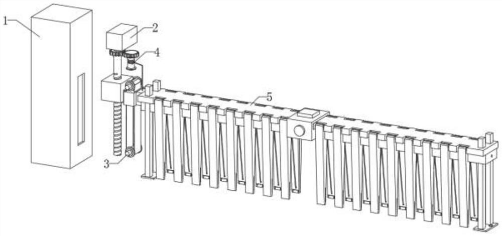
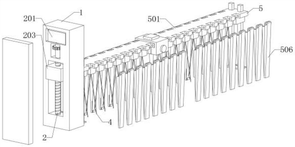
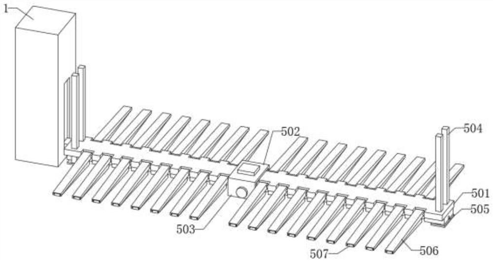
[0061] The present invention provides a rapid lifting system for barrier gates based on vehicle traffic, which includes a device outer box 1; the device outer box 1 is a hollow cuboid structure as a whole, and a square chute is provided on one side of the device outer box 1; a lifting control mechanism 2, The lifting control mechanism 2 is installed inside the device outer box 1 through the rotation of the rotating shaft; the lifting control mechanism 2 includes: a motor 201, which is fixedly installed inside the device outer box 1; an auxiliary tightening device 3, and the auxiliary tightening device 3 is installed outside the device The inside of the box 1; the protective device 4, which is rotatably installed inside the outer box 1 of the device, and the protective device 4 is slidably connected with the lifting control mechanism 2; the protective device 4 includes: a supporting rotating ring 401, and the number of s...


PUM


Abstract

The invention provides a barrier gate rapid lifting system based on vehicle passing. The barrier gate rapid lifting system comprises a device outer box; a lifting control mechanism which is rotationally mounted in the device outer box through a rotating shaft; a protection device which is rotationally mounted in the device outer box; and a protective fence mechanism is in sliding connection with the device outer box through the lifting control mechanism. By arranging the license plate sensing camera, the vehicle bottom sensing camera, the lifting control mechanism and the protective fence mechanism, when a vehicle passes, the protective fence mechanism can be rapidly lifted, and the passing speed of the vehicle is effectively increased; through the arrangement of the supporting fixing rods, the anti-collision performance of the protective fence mechanism is effectively improved, and the vehicle stopping effect of the device is greatly improved; and by arranging a protection device, the problem that external rainwater and sundries enter the device through a square sliding groove is effectively prevented.

Description

technical field [0001] The invention belongs to the technical field of vehicle barriers, and more specifically relates to a rapid lifting system for barriers based on vehicle traffic. Background technique [0002] Barrier gates, also known as car stoppers, are channel entrance and exit management equipment specially used to restrict motor vehicles on the road. They are now widely used in highway toll stations and parking lot systems to manage vehicle passages and to manage vehicle entry and exit. Modern barrier gate devices Basically, it is combined with wireless network for intelligent lifting management. [0003] For example, in the patent with the application number: 202011031513.0, the present invention relates to an intelligent vehicle barrier system based on image recognition and reading, including a barrier box, a rotating unit, a switch door, a manual controller, a camera, a barrier lever and a support mechanism, the support mechanism includes a support push rod ins...

Claims


Application Information

Patent Timeline
IPC IPC(8): E01F13/04G08G1/017
CPCE01F13/044G08G1/0175
Inventor 邵六先
Owner 邵六先
Learn More