
Railway signal lamp insulation installation and debugging ladder

A technology for railway signal lights, installation and debugging, applied in the direction of ladders, buildings, building structures, etc., can solve the problems of easily soiling clothes, hidden dangers, increasing the use of laborers, etc., and achieves the effect of stable contact parts and increased reliability.

Pending Publication Date: 2022-01-21
西安交通工程学院
View PDF5 Cites 0 Cited by
  • Summary
  • Abstract
  • Description
  • Claims
  • Application Information

AI Technical Summary

Problems solved by technology

[0003] During the use of the existing installation and debugging ladder, the signal ladder is usually leaned against the light pole. Since the pedals on the existing ladder are mostly cylindrical connecting rods or flat connecting rods, but the contact area between the pedals and the soles of the feet is relatively small. Small, there are certain safety hazards in rainy days or when the stepping is unstable. At the same time, in the process of leaning the ladder, in order to ensure its stability, another staff member is usually required to stabilize the ladder below, thus increasing the number of laborers. and after each use, a certain amount of dust will remain on the pedals of the ladder, making it easy for the staff to dirty the clothes when they are carried after use. Therefore, how to reasonably solve this problem is what we need to consider

Method used


Image

  • Railway signal lamp insulation installation and debugging ladder
  • Railway signal lamp insulation installation and debugging ladder
  • Railway signal lamp insulation installation and debugging ladder

Examples


Embodiment 1

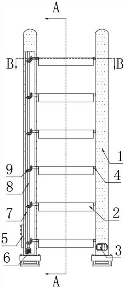
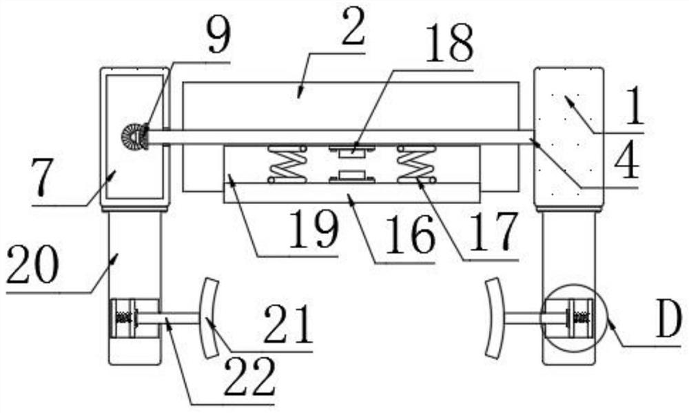
[0025] refer to Figure 1-5 , a railway signal lamp insulation installation and debugging ladder, comprising two vertical bars 1, a control panel 5 is installed on the left side of the vertical bar 1 on the left side, a power supply 3 is arranged in the vertical bar 1 on the right side, and the two vertical bars A plurality of first rotating rods 4 are rotatably connected between the adjacent surfaces of 1, and pedals 2 are set on the plurality of first rotating rods 4, and the plurality of pedals 2 are fixedly connected with the corresponding first rotating rods 4, located on the left The vertical rod 1 on the side is provided with a vertical chamber 7, and a rotating mechanism is provided in the vertical chamber 7. The rotating mechanism includes a driving motor 6 arranged at the bottom of the vertical chamber 7. The driving motor 6 is a three-phase AC motor, and the output of the driving motor 6 The end of the shaft is fixedly connected with a second rotating rod 8, the upp...

Embodiment 2

[0037] refer to Figure 6-7 , The difference between this embodiment and Embodiment 1 is that a transition chamber 29 and a contraction chamber 27 are provided in the vertical rod 1 on the right side, the contraction chamber 27 is located on the right side of the transition chamber 29, and a piston is arranged in the contraction chamber 27 33. The piston 33 is slidingly connected to the inner wall of the contraction cavity 27. The lower end of the piston 33 is elastically connected to the inner bottom of the contraction cavity 27 through the energizing spring 28. The power supply 3, the main switch and the energizing spring 28 form a circuit through wires. The contraction cavity 27 is located at The space above the piston 33 communicates with the outside world through the intake pipe 31. The space above the piston 33 communicates with the space on the right side of the transition chamber 29 through the air outlet pipe 32. The air inlet pipe 31 and the air outlet pipe 32 are pro...


PUM


Abstract

The invention discloses a railway signal lamp insulation installation and debugging ladder. The railway signal lamp insulation installation and debugging ladder comprises two vertical rods, a plurality of first rotating rods are rotationally connected between the adjacent surfaces of the two vertical rods, pedals are arranged on the plurality of first rotating rods in a sleeving mode, the plurality of pedals are fixedly connected with the corresponding first rotating rods, a vertical cavity is formed in the vertical rod located on the left side, and a rotating mechanism is arranged in the vertical cavity; and the rotating mechanism comprises a driving motor arranged at the bottom in the vertical cavity, the tail end of an output shaft of the driving motor is fixedly connected with a second rotating rod, and the upper end of the second rotating rod is rotationally connected with the inner top of the vertical cavity. According to the ladder, the rectangular pedals are adopted, and the pedals are always kept in a state of being parallel to the ground, so that workers can be prevented from slipping when climbing the ladder; and meanwhile, the contact part of the ladder and a lamp pole is more stable through an extrusion mechanism, and air flow can be blown to the pedals after each time of use, so that the cleanness of the pedals is guaranteed.

Description

technical field [0001] The invention relates to the technical field of debugging ladders, in particular to a ladder for insulation installation and debugging of railway signal lights. Background technique [0002] With the rapid development of domestic railway construction, the demand for equipment for railway signal installation is also increasing rapidly, especially during the installation and maintenance of railway signal lights, staff often need to use installation and debugging ladders to install and maintain signal lights, in order to avoid work There is a risk of electric shock during the installation process, and installation and debugging ladders made of insulating materials are often used. However, the existing installation and debugging ladders still have the following problems during use: [0003] During the use of the existing installation and commissioning ladder, the signal ladder is usually leaned against the light pole, because most of the pedals on the exis...

Claims


Application Information

Patent Timeline
Patent Type & Authority Applications(China)
IPC IPC(8): E06C7/08E06C7/00E06C7/50
CPCE06C7/081E06C7/082E06C7/50E06C7/00
Inventor 杜巧玲罗永吴文艾张治国
Owner 西安交通工程学院
Learn More