Indoor visible light positioning system and method based on image sensing technology

A positioning system and positioning method technology, applied in positioning, short-range systems, radio wave measurement systems, etc., can solve problems such as inapplicable positioning, inability to complete positioning, interference, etc., and achieve the effect of improving anti-occlusion ability

Pending Publication Date: 2022-01-21
SOUTH CENTRAL UNIVERSITY FOR NATIONALITIES
View PDF0 Cites 0 Cited by
  • Summary
  • Abstract
  • Description
  • Claims
  • Application Information

AI Technical Summary

Problems solved by technology

However, these positioning methods are susceptible to interference from indoor multipath signals, and cannot complete positioning when the occlusion is severe, and are not suitable for positioning high-speed moving objects, etc.

Method used


Image

  • Indoor visible light positioning system and method based on image sensing technology
  • Indoor visible light positioning system and method based on image sensing technology
  • Indoor visible light positioning system and method based on image sensing technology

Examples


Embodiment Construction

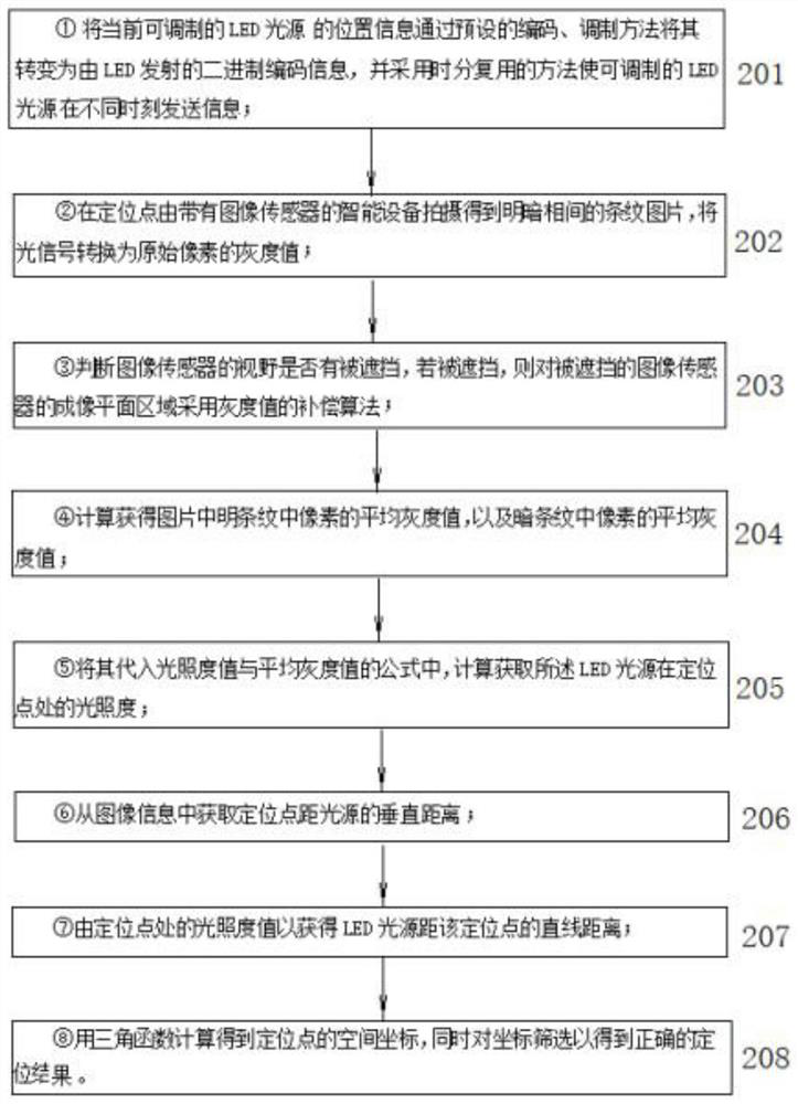
[0045] Below in conjunction with accompanying drawing and embodiment describe in detail:

[0046] 1. System

[0047] 1. Overall

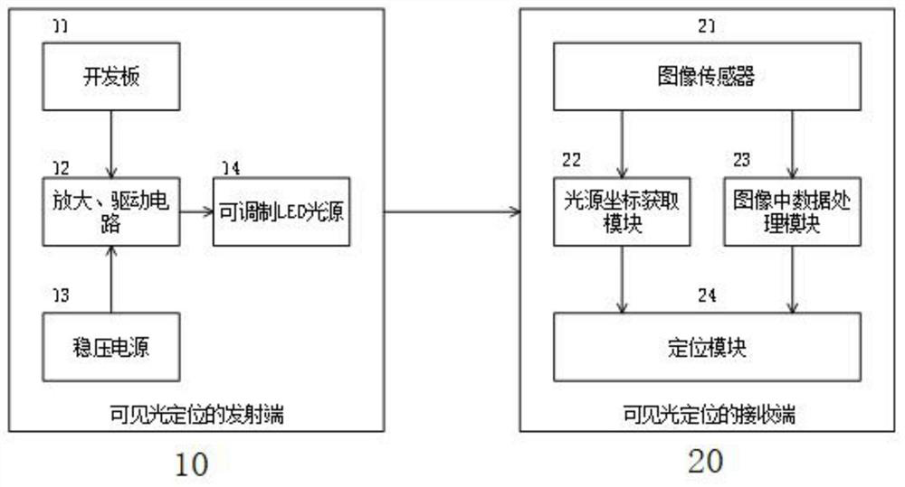
[0048] Such as figure 1 , the system is composed of a transmitting end 10 for visible light positioning and a receiving end 20 for visible light positioning connected front and back;

[0049] The transmitting end 10 of visible light positioning is composed of a development board 11, an amplification and driving circuit 12, a regulated power supply 13 and a modulatable LED light source 14. 13 is connected with amplification, drive circuit 12;

[0050] The receiving end 20 of visible light positioning includes an intelligent terminal device with an image sensor 21, and is embedded with a light source coordinate acquisition module 22, an image data processing module 23, and a positioning module 24. The light source coordinate acquisition module 22 and image data processing module 23 are respectively connected with The positioning module 24 interact...


PUM


Abstract

The invention discloses an indoor visible light positioning system based on an image sensor and a method thereof, and relates to an optical communication positioning technology. The system is composed of a visible light positioning transmitting end and a visible light positioning receiving end which are connected front and back. The development board, the amplifying and driving circuit and the modulatable LED light source are connected in sequence, and the stabilized power supply is connected with the amplifying and driving circuit; wherein the visible light positioning receiving end is an intelligent terminal device with an image sensor, a light source coordinate acquisition module, an in-image data processing module and a positioning module are embedded in the receiving end, and the light source coordinate acquisition module and the in-image data processing module interact with the positioning module. Compared with the prior art, the method has the following advantages and positive effects: (1) the image sensor is used for obtaining the illuminance value; (2) a gray scale compensation method for shielding pixels; (3) an intelligent terminal rotation coordinate screening method; (4) visible light positioning is completed in real time during visible light communication.

Description

technical field [0001] The invention relates to optical communication positioning technology, in particular to an image sensor-based indoor visible light positioning system and a method thereof. Background technique [0002] Satellite positioning systems (BDS, GPS, GNSS, GSNS) can provide real-time positioning and navigation. However, in closed environments such as indoors, the positioning and navigation of satellite positioning systems are inaccurate and discontinuous, because the signals transmitted by satellites are usually Clouds, ceilings, walls and other obstacles hinder and attenuate or even interrupt, which has become a hot topic in location services - the "last meter" issue. Wi-Fi, Bluetooth, Radio Frequency Identification (RFID), Ultrasound, Ultra-Wideband and ZigBee have been proposed to improve the performance of indoor positioning, but due to the limitations of radio waves As well as the limitations of factors such as low positioning accuracy and high deploymen...

Claims


Application Information

Patent Timeline
Patent Type & Authority Applications(China)
IPC IPC(8): G01C21/00G01C21/20G01S5/16H04B10/116
CPCG01C21/00G01C21/206G01S5/16H04B10/116
Inventor 杨春勇王猛进倪文军侯金陈少平
Owner SOUTH CENTRAL UNIVERSITY FOR NATIONALITIES
Why Eureka
Try Eureka