Fluorescent optical fiber temperature measurement system and method based on wireless sensing
What is AI technical title?
AI technical title is built by Patsnap AI team. It summarizes the technical point description of the patent document.
A fluorescent optical fiber and wireless sensing technology, applied in the field of fluorescent optical fiber temperature measurement system, can solve the problem of inaccurate measurement
Active Publication Date: 2022-08-09
中国电建集团海南电力设计研究院有限公司
View PDF11 Cites 0 Cited by
Summary
Abstract
Description
Claims
Application Information
AI Technical Summary
This helps you quickly interpret patents by identifying the three key elements:
Problems solved by technology
Method used
Benefits of technology
Problems solved by technology
[0004] At present, the conventional method is to simulate or calculate the temperature value, but it cannot be accurately measured. Therefore, it is urgent to provide a system or method that can measure the actual temperature value of the winding to solve this problem
Method used
Image
Click on the blue label to locate the original text in one second.
Reading with bidirectional positioning of images and text.
Examples
Embodiment 1
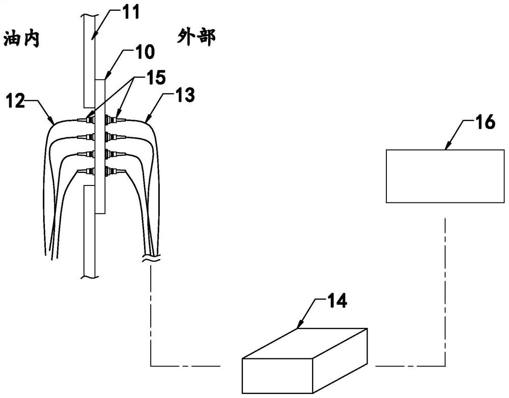
[0092] like figure 1 As shown, the present invention discloses a fluorescent optical fiber temperature measurement system based on wireless sensing, which is characterized in that: comprising:
[0093] The through plate 10 is installed on the transformer tank wall 11 and has several optical fiber interfaces;
[0094] The oil-resistant optical fiber 12 is located in the transformer oil tank, and one end extends to the optical fiber interface, and the other end extends to the transformer winding, and an optical fiber probe is provided at this end;
[0095] The optical fiber jumper 13 is located outside the transformer, and one end extends to the optical fiber interface, and the other end is connected with the optical fiber temperature controller 14;
[0096] The through device 15 is arranged at each optical fiber interface, and is used to connect the oil-resistant optical fiber 12 and the optical fiber jumper 13;
[0097] The serial server 16 is connected with the optical fibe...
Embodiment 2
[0101] Embodiment 2, the difference with embodiment 1 is:
[0102] like Figure 2-Figure 9 shown:
[0103] In a specific embodiment of the present invention, it also includes:
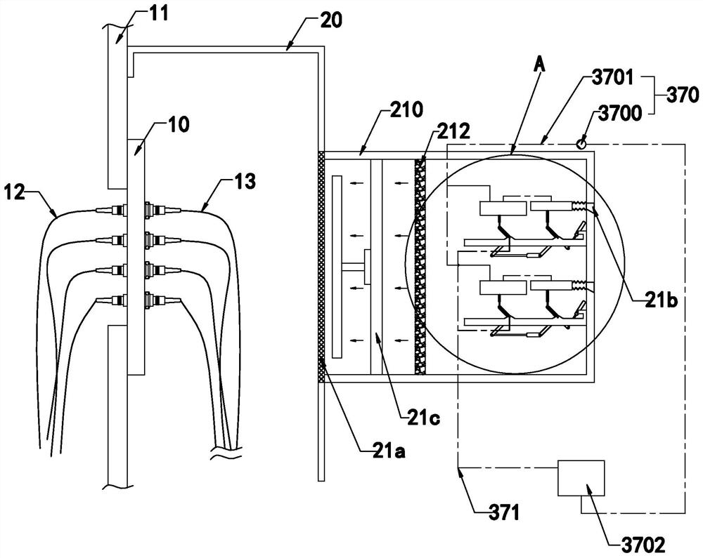
[0104] The protective cover 20 is installed on the transformer tank wall 11, and can cover and accommodate the through plate 10, the optical fiber jumper 13 and the optical fiber temperature controller 14;
[0105] The cooling device 21 is arranged on any side of the protective cover 20, and has at least an air inlet end, an air outlet end and an air source 21c, when the air source 21c is activated, it can generate an air flow flowing from the air inlet end to the air outlet end;
[0106] The cooling device 21 at least has a housing 210, a cooling part and a dehumidifying part 212, and the air inlet end is arranged on the housing 210. When the air source 21c is activated, the air flow passes through the cooling part and the dehumidifying part 212 and enters the protection inside the cover 20.
[01...
PUM
Abstract
The invention relates to a fluorescent optical fibertemperature measurementsystem based on wireless sensing and a method thereof, which are characterized by comprising: a through plate, which is installed on the wall of a transformeroil tank and has several optical fiber interfaces; an oil-resistant optical fiber, which is located in the transformeroil tank, And one end extends to the optical fiber interface, the other end extends to the transformer winding, and an optical fiber probe is arranged at this end; the optical fiberjumper is located outside the transformer, and one end extends to the optical fiber interface, and the other end is connected with an optical fiber Temperature controller; through device, set at each optical fiber interface, and used to connect oil-resistant optical fiber and optical fiber jumper; serial server, connected to the optical fiber temperature controller, and wirelessly connected to a background computer; can detect the actual temperature of the transformer winding.
Description
technical field [0001] The invention relates to the technical field of temperature measurement of transformer windings, in particular to a fluorescent optical fiber temperature measurementsystem and method based on wireless sensing. Background technique [0002] Transformer refers to a device that uses the principle of electromagnetic induction to change the AC voltage. Its main components are the primary coil, the secondary coil and the iron core (or magnetic core). [0003] During the use of the transformer, when an overload occurs, the transformer usually bears the brunt. Therefore, it is very important to monitor the thermoelectricity of the transformer winding, which can protect the transformer from damage or even excessive use. [0004] At present, the conventional method is to simulate or calculate the temperature value, but it cannot be accurately measured. Therefore, it is urgent to provide a system or method capable of measuring the actual temperature value of the...
Claims
Application Information
Patent Timeline
Application Date:The date an application was filed.
Publication Date:The date a patent or application was officially published.
First Publication Date:The earliest publication date of a patent with the same application number.
Issue Date:Publication date of the patent grant document.
PCT Entry Date:The Entry date of PCT National Phase.
Estimated Expiry Date:The statutory expiry date of a patent right according to the Patent Law, and it is the longest term of protection that the patent right can achieve without the termination of the patent right due to other reasons(Term extension factor has been taken into account ).
Invalid Date:Actual expiry date is based on effective date or publication date of legal transaction data of invalid patent.

