Power distribution cabinet with temperature control monitoring system

A monitoring system and power distribution cabinet technology, which is applied in the direction of control/regulation system, temperature control, substation/power distribution device shell, etc., can solve problems such as property loss, insufficient heat dissipation, and potential safety hazards, and achieve life and property protection and recovery loss, damage reduction effect

Pending Publication Date: 2022-01-21
江苏鹏泰电气有限公司
View PDF0 Cites 1 Cited by
  • Summary
  • Abstract
  • Description
  • Claims
  • Application Information

AI Technical Summary

Problems solved by technology

If the power distribution cabinet works under unsuitable environmental conditions such as high temperature, it will have a great impact on the internal electrical performance, which will bring certain safety hazards. If the temperature is too high, the load will even cause a fire. If it is discovered at the first time, it will cause major property losses, and even cause harm to the health of the people who are using the equipment.
[0004] However, the acquisition of temperature monitoring data of power distribution cabinets in the prior art is mostly based on manual or semi-automatic, which consumes manpower, material resources and time for inspection. A certain potential safety hazard, resulting in property damage

Method used


Image

  • Power distribution cabinet with temperature control monitoring system
  • Power distribution cabinet with temperature control monitoring system
  • Power distribution cabinet with temperature control monitoring system

Examples


Embodiment Construction

[0019] In describing the present invention, it is to be understood that the terms "central", "lateral", "upper", "lower", "left", "right", "vertical", "horizontal", "top", The orientation or positional relationship indicated by "bottom", "inner", "outer", etc. is based on the orientation or positional relationship shown in the drawings, and is only for the convenience of describing the present invention and simplifying the description, rather than indicating or implying the referred device Or elements must have a certain orientation, be constructed and operate in a certain orientation, and thus should not be construed as limiting the invention. In addition, the terms "first" and "second" are used for descriptive purposes only, and cannot be interpreted as indicating or implying relative importance or implicitly specifying the quantity of indicated technical features. Thus, a feature defined as "first" and "second" may explicitly or implicitly include one or more of these featu...


PUM


Abstract

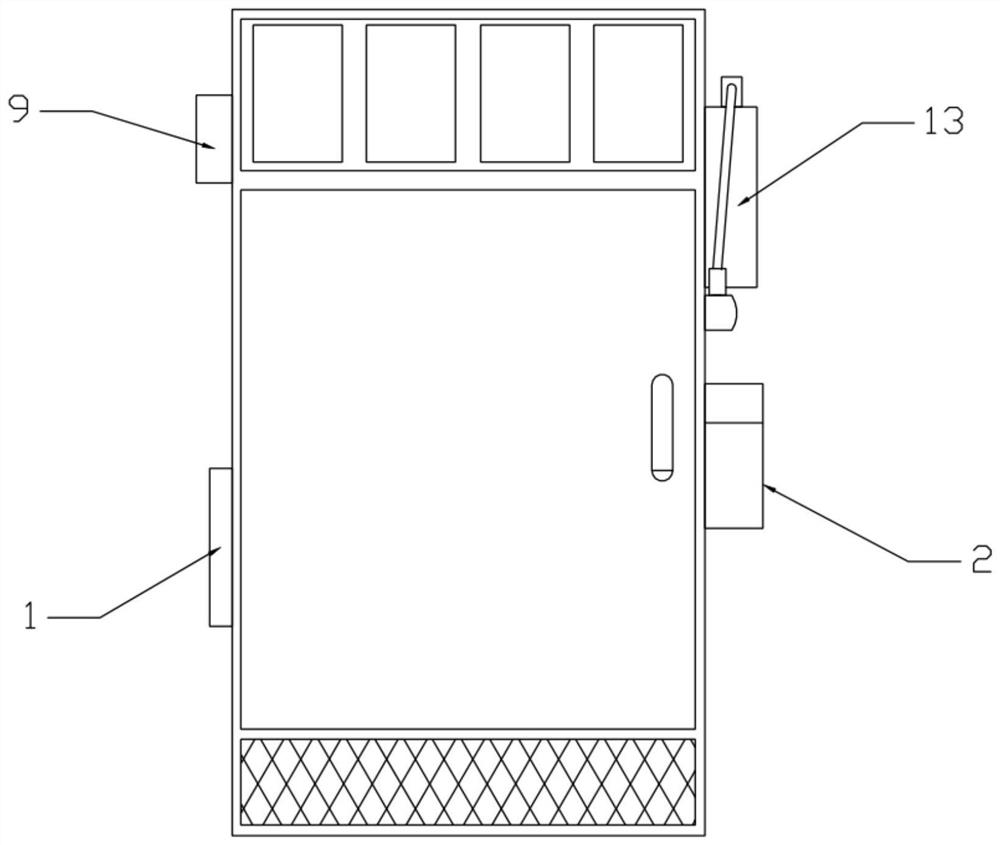
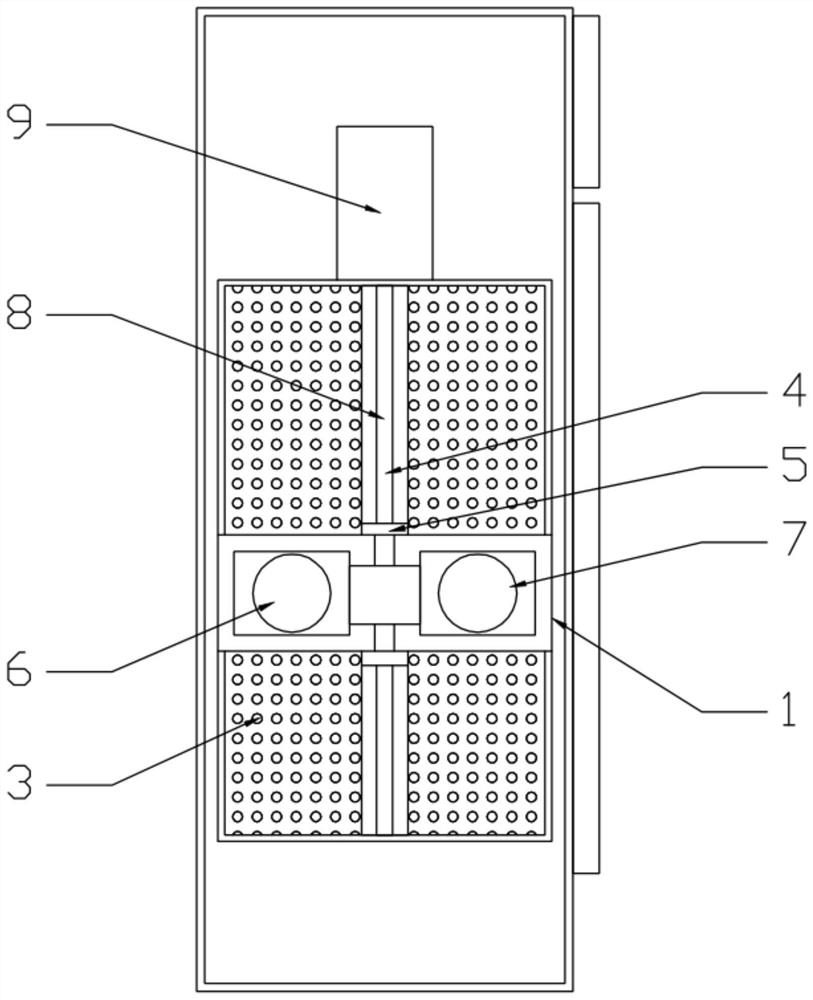
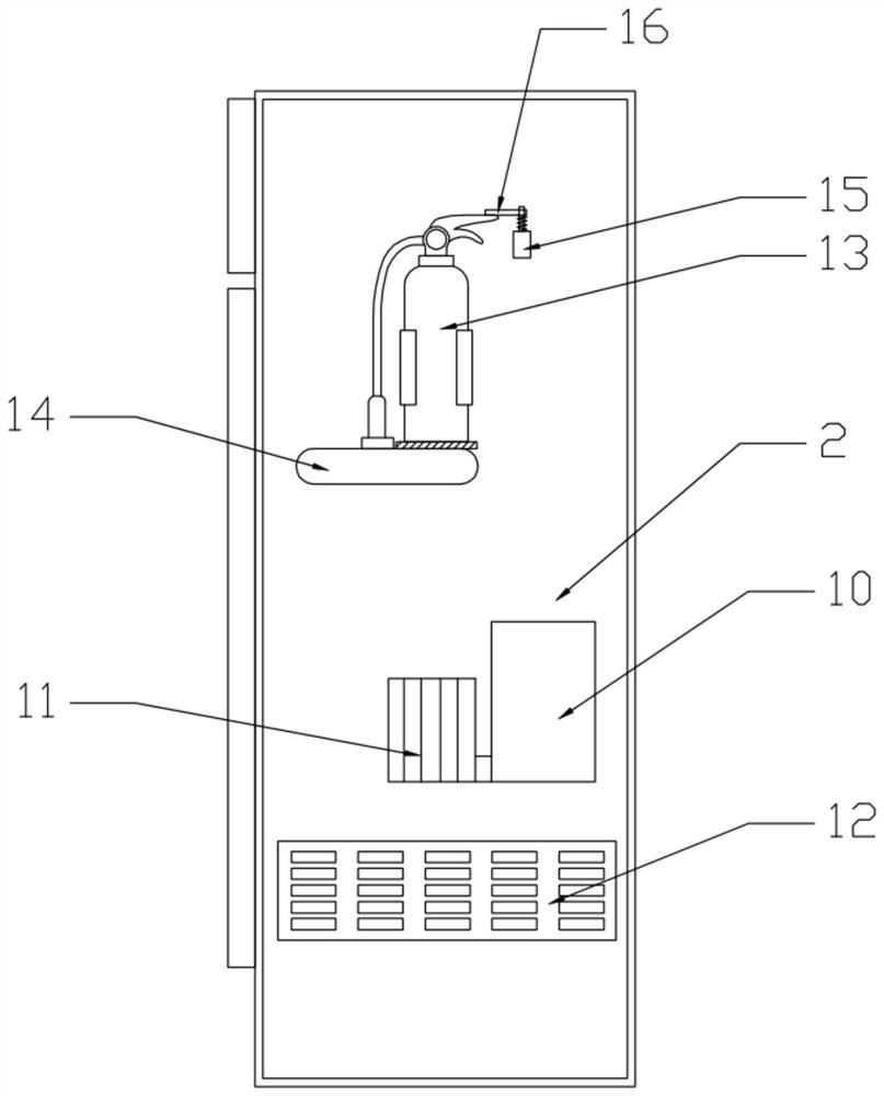
A power distribution cabinet with a temperature control monitoring system disclosed by the present invention comprises a cooling unit and a power distribution cabinet body. The cooling unit comprises a circulating air device and a refrigeration device which are arranged at two sides of the power distribution cabinet body, one side of the power distribution cabinet body is provided with an air outlet plate, and air outlet holes are uniformly distributed in the air outlet plate. An inward-concave lifting sliding groove is formed in the middle of the air outlet plate, the lifting sliding groove is vertically formed, a dovetail sliding block is arranged in the lifting sliding groove in a sliding mode, a circulating air device is fixedly arranged on the dovetail sliding block and comprises an air draft fan and a blowing fan which are arranged side by side, and the air draft fan and the blowing fan are communicated. And the outlet end of the air draft fan is communicated with the inlet end of the blowing fan. The defects in the prior art are overcome, the temperature in the power distribution cabinet is monitored in real time, cooling and even fire extinguishing can be conducted in time when workers do not arrive, property loss is effectively reduced, and the heat dissipation effect is good.

Description

technical field [0001] The invention relates to the technical field of power distribution cabinets, in particular to a power distribution cabinet with a temperature control monitoring system. Background technique [0002] As an important equipment on various power distribution equipment, the safe and stable operation of the power distribution cabinet is extremely important to people's daily life and factory production. Its functions and properties are extremely important, especially the multiple control cabinets placed in a row , once a high temperature or fire risk occurs, it will affect other power distribution cabinets, which is a huge loss for important equipment or expensive control cabinets. [0003] During long-term operation, the working environment conditions in the power distribution cabinet may change due to changes in ambient temperature, ambient humidity, or heating of electrical equipment. If the power distribution cabinet works under unsuitable environmental ...

Claims


Application Information

Patent Timeline
Patent Type & Authority Applications(China)
IPC IPC(8): H02B1/32H02B1/56G05D23/20H02B1/28A62C3/16G08B17/06G08B25/08
CPCH02B1/32H02B1/565G05D23/20H02B1/28A62C3/16G08B17/06G08B25/08
Inventor 王佳
Owner 江苏鹏泰电气有限公司
Why Eureka
Try Eureka