Dynamic reactive power compensation site selection method suitable for multi-infeed direct current system

A multi-feed DC, multi-feed technology, applied in reactive power compensation, reactive power adjustment/elimination/compensation, AC network circuits, etc., can solve errors, bus weights can not fit the actual situation, do not consider dynamic Reactive power characteristics of reactive power compensation equipment, etc., to achieve the effect of improving site selection efficiency, accurate and reasonable site selection results, and reducing the amount of calculation

Pending Publication Date: 2022-01-21
STATE GRID ZHEJIANG NINGBO YINZHOU POWER SUPPLY LTD CO +1
View PDF11 Cites 0 Cited by
  • Summary
  • Abstract
  • Description
  • Claims
  • Application Information

AI Technical Summary

Problems solved by technology

However, the existing site selection schemes for dynamic reactive power compensation equipment are all designed based on the static voltage stability factor VSF. This method does not take into account the reactive power characteristics of the dynamic reactive power compensation equipment itself, resulting in the given There will be a certain error between the site selection plan of the compensation equipment and the actual situation
When determining the position of dynamic reactive power compensation, it is necessary to select the weight of the busbar. In the prior art, it is generally believed that the weight of the commutation busbar with a larger load is larger. High-voltage hub busbars, etc. These buses play a vital role in the stability of the power system, but the loads they carry are not much. It can be seen that the selection of busbar weights in the prior art cannot meet the actual situation. It is also difficult to guarantee the rationality of the site selection scheme for dynamic reactive power compensation

Method used


Image

  • Dynamic reactive power compensation site selection method suitable for multi-infeed direct current system
  • Dynamic reactive power compensation site selection method suitable for multi-infeed direct current system
  • Dynamic reactive power compensation site selection method suitable for multi-infeed direct current system

Examples


Embodiment

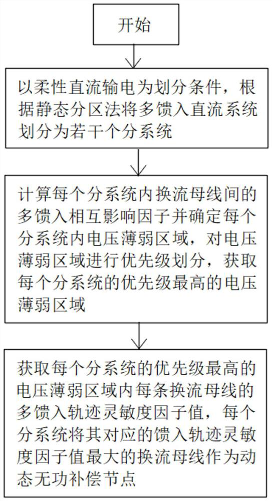
[0030] A site selection method for dynamic reactive power compensation suitable for multi-infeed DC systems, such as figure 1 shown, including the following steps:

[0031] Step 1. Taking the flexible DC transmission as the division condition, the multi-infeed DC system is divided into several subsystems according to the static partition method;

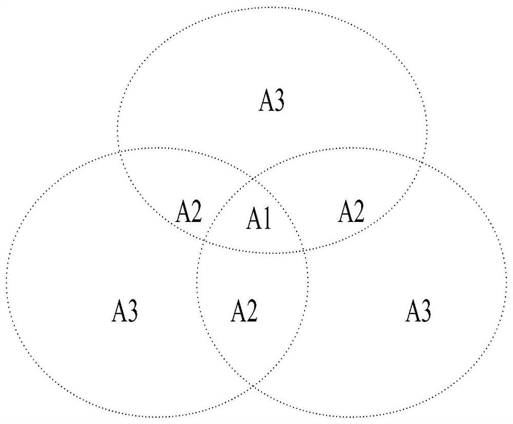
[0032] Step 2: Calculate the multi-infeed interaction factor between the converter buses in each subsystem, determine all voltage weak areas in each subsystem according to the multi-infeed interaction factor, and then determine each voltage weak area according to the overlapping number of voltage weak areas The priority of each voltage weak area in each subsystem, and select the voltage weak area with the highest priority in each subsystem;

[0033] Step 3: Select the voltage weak area with the highest priority in one of the sub-systems, obtain the information of all commutation buses in the voltage weak area, and calculate the mult...


PUM


Abstract

The invention provides a dynamic reactive power compensation site selection method suitable for a multi-infeed direct current system. The method specifically comprises the steps: dividing the multi-infeed direct current system into a plurality of subsystems, and calculating a multi-infeed mutual influence factor between commutation buses in each subsystem; and dividing all voltage weak areas of each sub-system according to the multi-infeed mutual influence factor, selecting the voltage weak area with the highest priority of each sub-system according to the overlapped number of the voltage weak areas, and obtaining a current conversion bus with the maximum multi-infeed track sensitivity factor value in each subsystem as a dynamic reactive compensation node corresponding to each sub-system. According to the invention, the calculation amount is reduced by dividing subsystems and screening the voltage weak area with the highest priority, the site selection efficiency of dynamic reactive compensation is further improved, and when the multi-infeed track sensitivity factor serving as the site selection basis is calculated, comprehensive assignment is performed on the bus weight so that the calculation result is more practical.

Description

technical field [0001] The invention relates to the technical field of reactive power compensation, in particular to a dynamic reactive power compensation site selection method suitable for multi-infeed DC systems. Background technique [0002] With the development of high-voltage direct current transmission technology in China, high-voltage projects are also under rapid construction, but with the construction of high-voltage projects, the problem of too dense DC landing points in regional power grids follows. If a commutation failure occurs in one of the DC systems in the multi-infeed DC system, it may cause commutation failures in nearby DC systems as well. The installation of dynamic reactive power compensation equipment can quickly and effectively improve the voltage recovery efficiency after commutation failure, and reduce the phenomenon of cascading commutation failure. Due to the high cost of dynamic reactive power equipment, it is necessary to reasonably arrange the...

Claims


Application Information

Patent Timeline
Patent Type & Authority Applications(China)
IPC IPC(8): H02J3/18
CPCH02J3/1871H02J2203/20Y02E40/30
Inventor 雷前潘妍黄继明徐任超张科波刘巽梁曹雅素杨跃平徐科兵
Owner STATE GRID ZHEJIANG NINGBO YINZHOU POWER SUPPLY LTD CO
Why Eureka
Try Eureka