

Driving equipment capable of assisting vehicle to steer stably based on new energy vehicle
A technology for new energy vehicles and driving equipment, applied in steering mechanisms, vehicle components, mechanical steering gears, etc., can solve the problems of unstable steering power, prone to sideslip, and overturning, and reduce the probability of accidents. Effect
- Summary
- Abstract
- Description
- Claims
- Application Information
AI Technical Summary
Problems solved by technology
Method used
Image

Examples
Embodiment 1
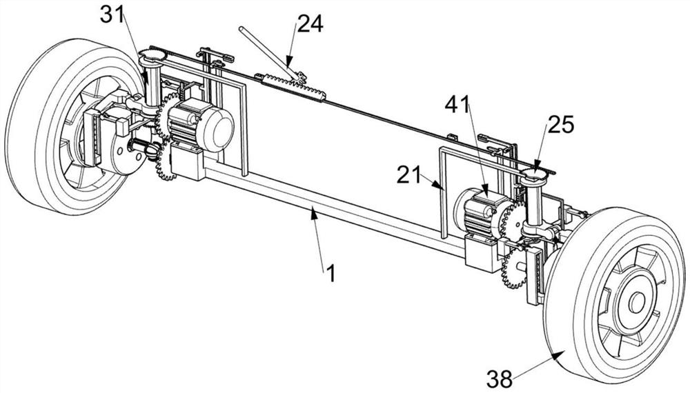
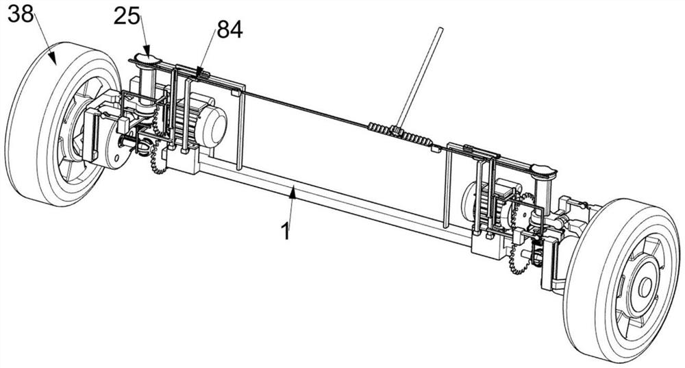
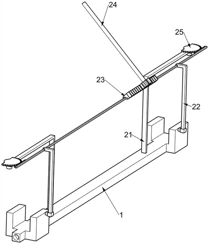
[0045] A driving device based on new energy vehicles that can assist the vehicle to stabilize steering, such as figure 1 , figure 2 , image 3 , Figure 4 , Figure 5 , Figure 6 , Figure 7 , Figure 8 and Figure 9 As shown, it includes a suspension 1, an L-shaped support frame 21, an N-shaped slotted frame 22, a sliding rack frame 23, a runner 24, a sector gear 25, a shock absorbing assembly 3 and a driving assembly 4, and on the suspension 1 Two L-shaped support frames 21 are fixedly installed, and the N-shaped slotted frame 22 is symmetrically arranged on the suspension 1. The two N-shaped slotted frames 22 are jointly slidably connected with a sliding rack frame 23, and the steering wheel shaft of the automobile is fixedly connected with a The runner 24, the runner 24 meshes with the sliding rack frame 23, the bearing on the L-shaped support frame 21 is connected with a sector gear 1 25 through an interference fit, and the sector gear 1 25 meshes with the sliding...
Embodiment 2
[0051] On the basis of Example 1, such as Figure 10 , Figure 11 , Figure 12 and Figure 13 As shown, it also includes a cornering deceleration assembly 5, the suspension 1 is provided with a cornering deceleration assembly 5, the cornering deceleration assembly 5 is used to decelerate when the car turns, and the cornering deceleration assembly 5 includes a special-shaped slotted frame 51, Sector gear two 52, push rack frame 53, the 4th back-moving spring 54, rectangular slide rail frame 55, push ring 56 and the 5th back-moving spring 57, are fixedly connected with two special-shaped slotting frames 51, special-shaped articulated frame on suspension 1 The bottom of 34 is fixedly connected with sector gear 2 52, and the special-shaped slotted frame 51 is slidably connected with a push rack frame 53, which is engaged with the sector gear 2 52, and is connected with a fourth return spring on the push rack frame 53 54, one end of the fourth return spring 54 away from the push...
Embodiment 3
[0055] On the basis of Example 2, such as Figure 12 , Figure 13 and Figure 14 As shown, it also includes a two-stage deceleration assembly 6. The output shaft of the driving motor 41 is provided with a two-stage deceleration assembly 6. The two-stage deceleration assembly 6 is used to directly reduce the driving speed of the vehicle to the minimum. The two-stage deceleration assembly 6 includes a drive Slot element plate 62, sliding block 63, sixth return spring 64, slotted gear 65, special-shaped rack frame 66, L-shaped slide bar 67, seventh return spring 68 and return spring 69, set on the output shaft of drive motor 41 There is a slotted element disc 62, and the slotted element disc 62 is slidably connected with a sliding block 63 in a circumferentially distributed manner, and a sixth return spring 64 is connected between the sliding block 63 and the slotted element disc 62, and the slotted element disc 62 Slotted gear 65 is sheathed on, and slotted gear 65 is provided...
PUM
 Abstract
Description
Claims
Application Information