Mounting structure of dynamic damper

A technology for installing structures and dampers, which is applied in the directions of shock absorbers, shock absorbers, supporting machines, etc., can solve the problems of falling off of mass components 12 and breaking of supporting rubber elastic bodies 16, so as to achieve the effect of restraining damage and reducing impact.

Active Publication Date: 2022-01-25
TOYO TIRE & RUBBER CO LTD
View PDF7 Cites 0 Cited by
  • Summary
  • Abstract
  • Description
  • Claims
  • Application Information

AI Technical Summary

Problems solved by technology

Such a dynamic damper uses the vibration of the mass member 12 passing through the supporting rubber elastic body 16 to reduce the vibration of the vibrat

Method used


Image

  • Mounting structure of dynamic damper
  • Mounting structure of dynamic damper
  • Mounting structure of dynamic damper

Examples


Embodiment Construction

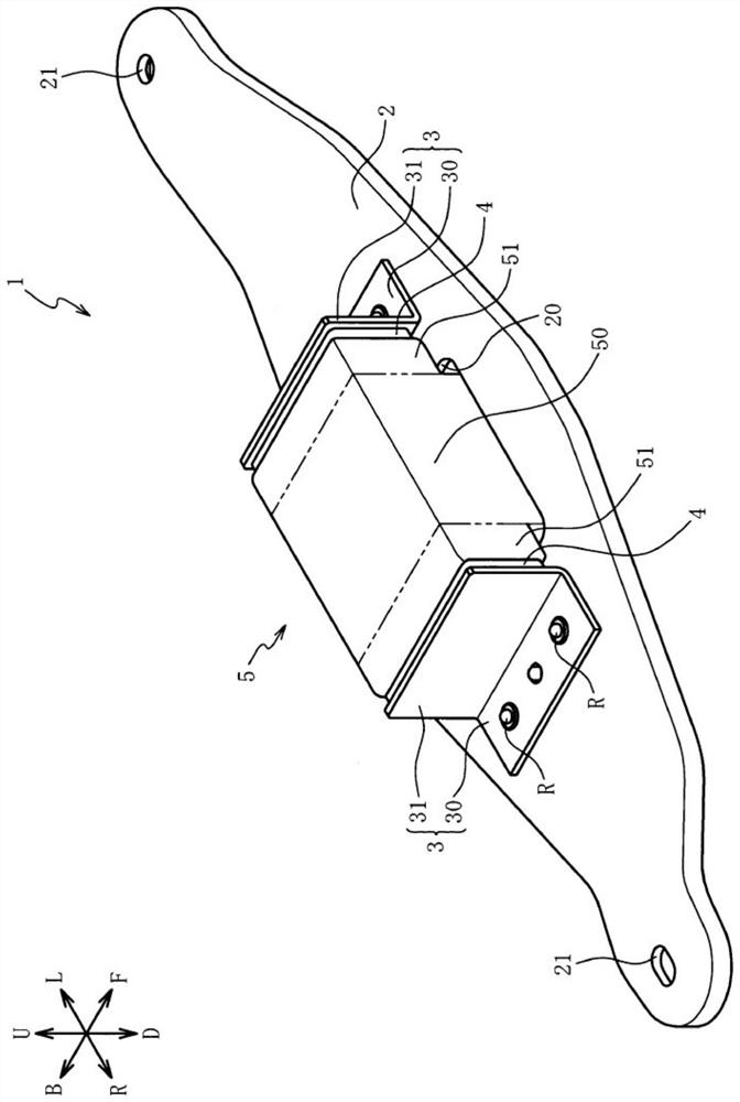
[0044] Hereinafter, preferred embodiments of the present invention will be described with reference to the drawings. First, refer to figure 1 The overall structure of the dynamic damper 1 according to the first embodiment of the present invention will be described. figure 1 It is a front perspective view of the dynamic damper 1 of the first embodiment. also, figure 1 Arrows U-D, L-R, and F-B in , represent the up-down direction, left-right direction, and front-rear direction of the dynamic damper, respectively, and the same applies to the following figures. In addition, in the first embodiment, the up-down direction of the dynamic damper 1 corresponds to the "first direction", the left-right direction corresponds to the "second direction", and the front-rear direction corresponds to the "third direction". The same applies to the embodiments.

[0045] In addition, although the up-down direction, the left-right direction, and the front-rear direction of the dynamic damper...


PUM


Abstract

A mounting structure of a dynamic damper capable of effectively reducing the vibration of a vibration body is provided. The mounting structure includes a suspension member 100 inhibiting the upward shift of a mass member 5. The suspension member 100 and plates 3 are configured as separate members, so that as compared with the case where a pair of plates 3 are coupled, the opposite interval between the plates 3 can be determined without being affected by the dimension accuracy of such the coupling portion. Thus, the thicknesses of the rubber elastic bodies 4 can foe formed at high accuracy, so that the mass member 5 can be easily vibrated at the desired frequency. Therefore, the vibration of the suspension member 100 can be effectively reduced.

Description

technical field [0001] The invention relates to an installation structure of a dynamic damper, in particular to an installation structure of a dynamic damper capable of effectively reducing the vibration of a vibrating body. Background technique [0002] There is known a technique for reducing the vibration of the vibrating body by using the dynamic damper by attaching the dynamic damper to the vibrating body of the vehicle. For example, Patent Document 1 describes a dynamic damper that includes: a mounting member 30 (bracket) mounted on an axle housing 62 (vibrating body); a door-shaped member 28 fixed to the mounting member 30; and The mass member 12 is elastically supported by the gate member 28 via the supporting rubber elastic body 16 . Such a dynamic damper uses the vibration of the mass member 12 that passes through the supporting rubber elastic body 16 to reduce the vibration of the vibrating body. Therefore, the repeated vibration of the mass member 12 may break th...

Claims


Application Information

Patent Timeline
IPC IPC(8): F16F15/08F16F15/02
CPCF16F15/08F16F15/02B60G13/16B60G2202/25B60G2206/41B60G2206/73B60G2800/162B60G13/005F16F7/108F16F2230/36F16M13/02F16F2222/08F16F2224/025F16F2224/0208F16F2230/0005
Inventor 方村知行山本彦文
Owner TOYO TIRE & RUBBER CO LTD
Why Eureka
Try Eureka