Check patentability & draft patents in minutes with Patsnap Eureka AI!

Method and system for magnetizing elements of magnetic field sensor arrangement

A technology of magnetic field sensor and magnetized magnetic field, which is applied in the direction of magnetization intensity measurement, instruments, measuring devices, etc., and can solve problems such as wrong orientation

Pending Publication Date: 2022-01-25
ROBERT BOSCH GMBH
View PDF3 Cites 0 Cited by
  • Summary
  • Abstract
  • Description
  • Claims
  • Application Information

AI Technical Summary

Problems solved by technology

This can lead to at least partial misorientation of the layer to be magnetized

Method used


Image

  • Method and system for magnetizing elements of magnetic field sensor arrangement
  • Method and system for magnetizing elements of magnetic field sensor arrangement
  • Method and system for magnetizing elements of magnetic field sensor arrangement

Examples


Embodiment Construction

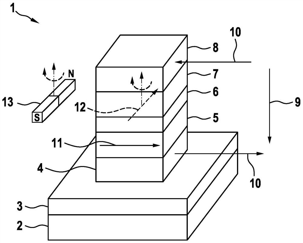
[0023] figure 1 The magnetic field sensor 1 is shown schematically in a perspective view. The magnetic field sensor 1 is based, for example, on the principle of magnetic tunnel resistance (English: tunnel magnetoresistance, tunnel magnetoresistance, TMR). Therefore, the magnetic field sensor 1 can also be referred to as a TMR sensor 1 .

[0024] The magnetic field sensor 1 has a substrate 2 . For example, substrate 2 can comprise silicon. However, substrate 2 can also comprise other materials, for example other semiconductors and / or semiconductor oxides. The magnetic field sensor 1 also has an integrated circuit 3 (English: integrated circuit, IC) arranged on a substrate 2 . For example, integrated circuit 3 can be provided for operating magnetic field sensor 1 .

[0025]An electrically conductively embodied lower contact element 4 is arranged above the substrate 2 . A lower ferromagnetic layer 5 is arranged on the lower electrical contact element 4 . The lower ferromag...


PUM


Abstract

A magnetic field sensor arrangement has a plurality of sensor segments, each having a plurality of magnetic field sensors. A magnetizing current conductor is arranged in the region of the magnetic field sensor in such a way that elements of the magnetic field sensor can be magnetized. A plurality of half-bridges connected in parallel, each having a high switch pJ and a low switch nJ, each have a center tap connection arranged between the switches pJ and nJ. The magnetizing current conductor is connected to each center tap connection, so the magnetizing current conductor is divided into individually controllable magnetizing segments. In a method for magnetizing an element of a magnetic field sensor arrangement, an element of a sensor segment SJ is magnetized in such a way that two switches nJ and pJ + 1, or optionally pJ and nJ + 1, of two directly adjacent half-bridges, which are located at different potentials, are closed at the same time. In this case, at least one another switch nX < J or pY > J + 1 or alternatively pX < J or nY > J + 1 is closed.

Description

technical field [0001] The invention relates to a method and a system for magnetizing elements of a magnetic field sensor arrangement by means of a magnetization device. Background technique [0002] Magnetic field sensors based on the magnetoresistive effect are known from the prior art. Such a magnetic field sensor has two magnetized layers arranged one above the other and separated from one another by a separating layer. Here, the mean direction of magnetization of the pinned layer is fixed and cannot be changed in an external magnetic field, whereas the mean direction of magnetization of the free layer depends on the external magnetic field. By applying a voltage at the two magnetized layers, a current can flow which depends on the angle enclosed by the magnetization directions of the layers. [0003] If the external magnetic field exceeds a critical field strength, the magnetization of the free layer may be disturbed. Such a misorientation may lead to an increased no...

Claims


Application Information

Patent Timeline
IPC IPC(8): G01R33/09
CPCG01R33/09G01R33/0058G01R33/0052G01R33/1215G01R33/0017G01R33/0094G01R33/093G01R33/098G01R33/0029
Inventor B·恩格尔C·A·罗马尼G·德桑德雷J·阿尔茨纳P·马瑟M·马施曼
Owner ROBERT BOSCH GMBH
Features
  • R&D
  • Intellectual Property
  • Life Sciences
  • Materials
  • Tech Scout
  • Unparalleled Data Quality
  • Higher Quality Content
  • 60% Fewer Hallucinations
Learn More