Anti-seismic redundancy analysis method for transformer substation system

An analysis method and substation technology, applied in the direction of instruments, data processing applications, resources, etc., can solve the problems of improving the system's anti-seismic ability and lack of redundant quantitative analysis, etc., and achieve the effect of improving the anti-seismic ability of the system

Pending Publication Date: 2022-01-25
INST OF ENG MECHANICS CHINA EARTHQUAKE ADMINISTRATION
View PDF0 Cites 0 Cited by
  • Summary
  • Abstract
  • Description
  • Claims
  • Application Information

AI Technical Summary

Problems solved by technology

However, there is currently a lack of quantitative analysis methods for redundancy, and it is difficult to improve the system's anti-seismic capability.

Method used


Image

  • Anti-seismic redundancy analysis method for transformer substation system
  • Anti-seismic redundancy analysis method for transformer substation system
  • Anti-seismic redundancy analysis method for transformer substation system

Examples


Embodiment 1

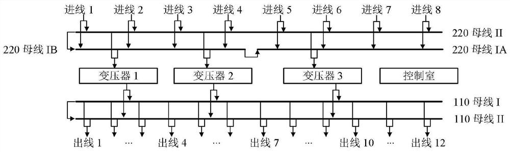
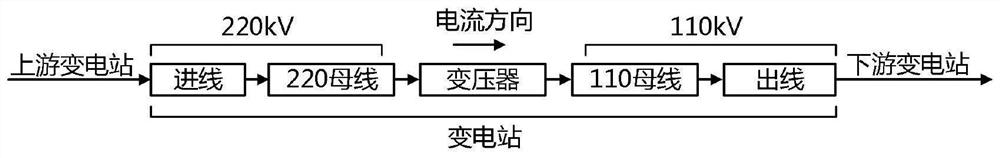
[0026] First introduce the substation. The substation is a complex system composed of a series of electrical equipment, including transformers, circuit breakers, isolating switches, current transformers, voltage transformers, lightning arresters, etc. These devices are connected to each other to form a complete and unified system. The function of transforming voltage and transmitting electric energy. A typical setup of a 220kV substation is as follows: figure 1 As shown, each component can be divided into five functional units: incoming line, 220kV busbar, transformer, 110kV busbar and outgoing line. The 220kV substation system includes 8 incoming lines, two 220kV busbars, 3 transformers, qualifying. In order to realize the functions of the substation system, the five functional units must work normally to form a complete path, such as figure 2 shown.

[0027] For substation systems, in order to meet the reliability of power supply, electrical equipment is mostly arranged ...

Embodiment approach

[0060] As an optional implementation, 1) may include:

[0061] Establish the state tree model of the substation system according to the relationship of each component in the substation system; set the state of the redundant functional unit to 0 according to the total redundant quantity of each redundant functional unit, and obtain the state tree model of the non-redundant system, And use the state tree model of the non-redundant system to calculate the performance index value of the first system; in the state tree model of the non-redundant system, the state of the actual redundant number of redundant functional units is no longer set to 0, and the partial redundancy is obtained The state tree model of the redundant system is used to calculate the performance index value of the second system by using the state tree model of the partially redundant system. After the redundant functional unit is added, the influence of the redundant functional unit on the seismic performance of ...


PUM


Abstract

The invention relates to an anti-seismic redundancy analysis method for a transformer substation system. The method comprises: dividing each component in the transformer substation system into a plurality of functional units, and determining redundant functional units in the transformer substation system and the total redundancy quantity of each redundant functional unit according to the value of a preset system performance index; then determining the actual redundancy number of each redundant function unit according to the actual redundancy demand, calculating the redundancy degree and the redundancy effect of each redundant function unit according to the actual redundancy number, and calculating the redundancy degree of the system according to the redundancy degrees and the redundancy effects of all the redundant function units; and finally, based on the association relationship between the system redundancy degree and the system redundancy effect, calculating the system redundancy effect according to the system redundancy degree, and then obtaining the system redundancy effect corresponding to the actual redundancy demand through calculation. The system redundancy is quantitatively analyzed, and the shock resistance of the system is evaluated; and weak links of the system can be improved according to quantitative analysis results, and the shock resistance of the system is improved.

Description

technical field [0001] The invention relates to the technical field of substation redundancy analysis, in particular to a method for analyzing the seismic redundancy of a substation system. Background technique [0002] At present, the design of the power system usually adopts the N-1 safety criterion. According to this criterion, after any independent component (generator, transmission line, transformer, etc.) of the N components of the power system fails and is cut off, it should not Cause power outages for users due to overload tripping of other lines, without destroying the stability of the system, and without accidents such as voltage collapse. Therefore, from the perspective of realizing functions, the power system has certain redundancy. However, there is currently a lack of quantitative analysis methods for redundancy, and it is difficult to improve the system's anti-seismic capability. Contents of the invention [0003] The purpose of the present invention is to...

Claims


Application Information

Patent Timeline
Patent Type & Authority Applications(China)
IPC IPC(8): G06Q10/06G06Q50/06
CPCG06Q10/06393G06Q50/06
Inventor 李吉超王涛尚庆学罗清宇
Owner INST OF ENG MECHANICS CHINA EARTHQUAKE ADMINISTRATION
Why Eureka
Try Eureka