Blocking device

A sealing device and sealing part technology, which is applied in the field of medical devices, can solve problems such as sealing failure and weakening, and achieve the effect of ensuring the sealing effect

Active Publication Date: 2022-06-21
LIFETECH SCI (SHENZHEN) CO LTD
View PDF0 Cites 0 Cited by
  • Summary
  • Abstract
  • Description
  • Claims
  • Application Information

AI Technical Summary

Problems solved by technology

[0005] Based on this, it is necessary to provide a new occlusion device for the problem that the occlusion device in the prior art is susceptible to pressure deformation and movement of the left atrial appendage leading to seal failure or weakening

Method used


Image

  • Blocking device
  • Blocking device
  • Blocking device

Examples


Embodiment 1

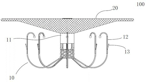
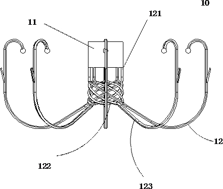
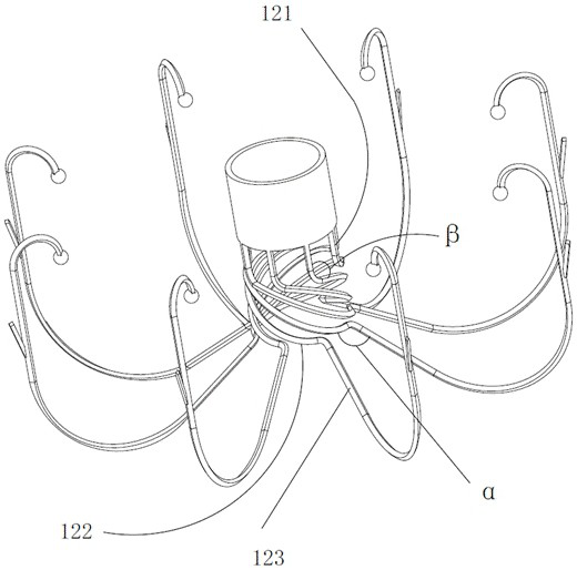
[0028] like Figure 1-3 shown, figure 1 It is a schematic structural diagram of the blocking device 100 in Embodiment 1 of the present invention. The blocking device includes a fixing part 10 and a sealing part 20 connected to the fixing part 10 , figure 2 It is a schematic structural diagram of the fixing part 10 of the blocking device 100 in Embodiment 1 of the present invention, image 3 It is a three-dimensional schematic diagram of the fixing part 10 of the sealing device 100 in Embodiment 1 of the present invention, and the sealing part 20 and the fixing part 10 are arranged at intervals along the axial direction of the sealing device 100 . The sealing part 20 is located at the proximal end of the blocking device 100 , and the fixing part 10 is located at the distal end of the blocking device 100 . The occlusion device 100 has a compressed state contained within the sheath for ease of delivery, as well as extending from the distal end of the sheath and self-expanding ...

Embodiment 2

[0047] The difference between the blocking device of Example 2 and Example 1 is that refer to Figure 4-6 , the deflection structure of the extension 322 does not include a helical structure, Figure 4 is the structural schematic diagram of the plugging device in the embodiment 2 of the present invention, Figure 5 It is a schematic structural diagram of the fixing part 30 of the blocking device in the second embodiment of the present invention, Image 6 It is a three-dimensional schematic diagram of the fixing part 30 of the blocking device in the second embodiment of the present invention.

[0048] In this embodiment, the fixing part 30 also includes a connecting piece 31 and a plurality of support rods 32 , and the proximal ends of the support rods 32 are fixed on the connecting piece 31 .

[0049] The inner side of the support rod 32 includes the connecting part 321, the extension part 322 and the expansion part 323 which are connected in sequence. It should be noted tha...


PUM


Abstract

The present invention relates to an occlusion device, comprising a fixing part for fixing the occlusion device at a predetermined position and a sealing part for sealing, the fixing part includes a connecting piece and several support rods, the connecting piece connects The support rod and the sealing part, the support rod includes a connection part and an expansion part connected in sequence from the proximal end to the distal end, the connection part is connected with the connection part, and the extension angle of the expansion part is relative to The extension angle of the connecting portion is deflected. This arrangement makes when the occlusion device is implanted, the stress of the left atrial appendage on the support rod of the occlusion device is shared in the radial direction, so that the component force of the stress in the axial direction becomes smaller, thereby making the axial deformation of the sealing part Or the axial movement becomes smaller to ensure the blocking effect of the blocking device.

Description

technical field [0001] The invention relates to the technical field of medical devices, in particular to a blocking device. Background technique [0002] In recent years, among patients with non-valvular atrial fibrillation, 90% of strokes due to atrial fibrillation originate from the left atrial appendage. There are clinical data showing that in the case of atrial fibrillation, removal of the left atrial appendage during cardiac surgery can reduce the incidence of stroke, suggesting the harm of the left atrial appendage in thromboembolism. Since the left atrial appendage is the fossa of the thrombus, blocking the opening of the left atrial appendage can eliminate the basis for thrombosis in the left atrial appendage. Usually, occlusion of the left atrial appendage with a left atrial appendage occluder is an effective way to prevent stroke caused by atrial fibrillation. [0003] In order to effectively occlude the left atrial appendage, it is necessary to implant the left ...

Claims


Application Information

Patent Timeline
Patent Type & Authority Patents(China)
IPC IPC(8): A61B17/00A61B17/12
CPCA61B17/0057A61B17/12A61B17/12031A61B17/12122A61B17/12159A61B2017/00659A61B2017/00615A61B2017/00632A61B17/12172
Inventor 李安宁刘建勇林志宏刘国良
Owner LIFETECH SCI (SHENZHEN) CO LTD
Why Eureka
Try Eureka