Semi-self-walking penstock mounting system and method

A pressure steel pipe and installation method technology, which is applied in metal processing equipment, metal processing, manufacturing tools, etc., can solve the problems of large slope changes, complex terrain, and lack of automatic running function, etc., and achieve the effect of low cost and improved work efficiency

Active Publication Date: 2022-01-28
CHINA RAILWAY JIUJIANG BRIDGE ENG +2
View PDF12 Cites 0 Cited by
  • Summary
  • Abstract
  • Description
  • Claims
  • Application Information

AI Technical Summary

Problems solved by technology

[0002] Water diversion projects generally have complex terrain and large gradient changes. The existing penstock installation methods all adopt the method of setting anchor points in front and pulling the portal frame through the traction mechanism; the existing methods have the following problems: 1. figure 1 As shown, the gantry under the existing installation method is all integrated design. The installation of the gantry generally lifts the steel pipe at the lifting station, and then walks the steel pipe to the design position through the tractor for installation. This transportation and installation use the same set of equipment , low efficiency; 2, such as figure 2 As shown, the existing penstock installation method can only install steel pipes on a single pipe; the installation of penstocks with multiple rows of penstocks side by side requires multiple tracks and multiple portal frames to meet the construction requirements; 3. The existing penstock installation equipment None of them have automatic running function, and must rely on the front traction device for walking

Method used


Image

  • Semi-self-walking penstock mounting system and method
  • Semi-self-walking penstock mounting system and method
  • Semi-self-walking penstock mounting system and method

Examples


Embodiment Construction

[0034] In order to achieve the above purpose and effects, the technical means and structures adopted in the present invention will be described in detail in terms of the features and functions of the preferred embodiments of the present invention in conjunction with the accompanying drawings.

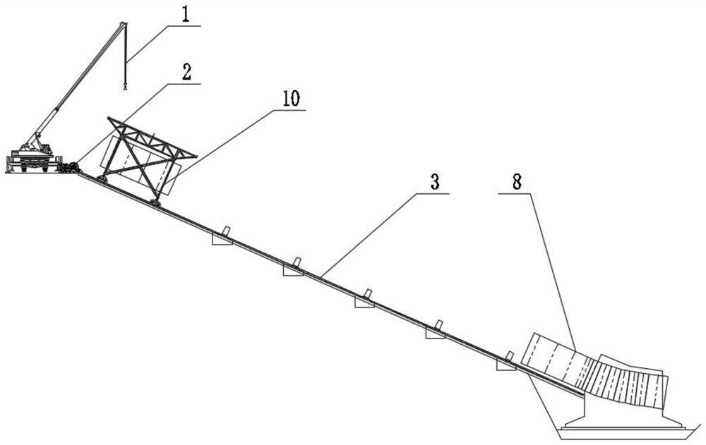
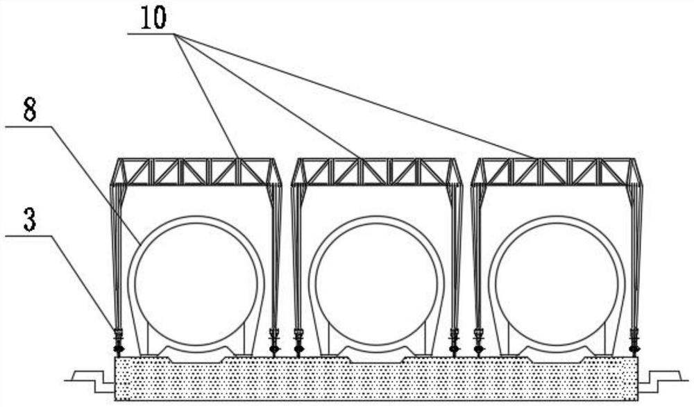
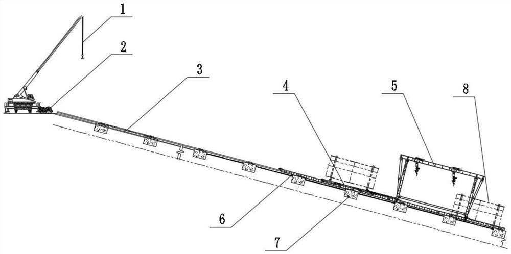
[0035] Such as Figure 3-6 As shown, the present invention provides a semi-self-propelled penstock installation system, including a lifting station 1, a tractor 2, a steel pipe delivery system and a pipe erection system;

[0036] The steel pipe delivery system includes a delivery track 3 and a pipe transport vehicle 4 arranged on the delivery track 3; the delivery track 3 is set on a slope, and the lifting station 1 and tractor 2 are arranged on the slope where the delivery track 3 is located The top; the end of the pipe transport vehicle 4 near the top of the slope is connected with the tractor 2 through a wire rope;

[0037] The tube erecting system includes a tube erecting track 6, ...


PUM


Abstract

The invention discloses a semi-self-walking penstock mounting system and method, and relates to the technical field of penstock mounting of water diversion engineering. The system comprises a lifting station, a traction machine, a penstock conveying system and a penstock erecting system. The penstock conveying system comprises a conveying rail and a penstock conveying vehicle arranged on the conveying rail; one end of the penstock conveying vehicle is connected with the traction machine; the penstock erecting system comprises a penstock erecting rail, a penstock erecting machine arranged on the penstock erecting rail and a rail traction mechanism; the end, close to the slope top end, of the penstock erecting machine is connected with the end, close to the slope top end, of the penstock erecting rail through an iron chain; the rail traction mechanism is a penstock conveying vehicle or a chain block; and self-walking of the penstock erecting machine or the whole of the penstock erecting machine and the penstock erecting rail is realized through the rail traction mechanism. The penstock erecting machine and the penstock conveying vehicle are designed in a separated mode, so that penstock conveying and penstock erecting operation can be conducted at the same time, and the working efficiency is improved; the penstock erecting machine can realize a self-walking function on a slope section within a certain range; and multiple parallel pipelines can be mounted at the same time.

Description

technical field [0001] The invention relates to the technical field of penstock installation in water diversion projects, in particular to a semi-self-propelled penstock installation system and method. Background technique [0002] Water diversion projects generally have complex terrain and large gradient changes. The existing penstock installation methods all adopt the method of setting anchor points in front and pulling the portal frame through the traction mechanism; the existing methods have the following problems: 1. figure 1 As shown, the gantry under the existing installation method is all integrated design. The installation of the gantry generally lifts the steel pipe at the lifting station, and the steel pipe is carried by the tractor to the design position for installation. This transportation and installation use the same set of equipment , low efficiency; 2, such as figure 2 As shown, the existing penstock installation method can only install steel pipes on a s...

Claims


Application Information

Patent Timeline
Patent Type & Authority Applications(China)
IPC IPC(8): B23P19/04B23P19/00
CPCB23P19/04B23P19/00Y02E10/20
Inventor 张延辉赵梦春朱东明李桐秦云张书豪梁辉向华李正兵周欢欢吴国栋齐晓敏陈阳光苏珊珊王琪文魏红桃张明杰李熊明郭旭龙王标郭成刘勇陈永明
Owner CHINA RAILWAY JIUJIANG BRIDGE ENG
Why Eureka
Try Eureka