Clamping fixture

A fixture and collet technology, applied in the field of clamping fixtures, can solve the problems of relatively high dimensional accuracy and surface roughness, large machining accuracy errors, uncontrollable clamping force, etc., and achieves low operation difficulty and clamping stability. High, positioning stability and consistent results

Pending Publication Date: 2022-01-28
SHENZHEN FLYTA TECH DEV
View PDF6 Cites 1 Cited by
  • Summary
  • Abstract
  • Description
  • Claims
  • Application Information

AI Technical Summary

Problems solved by technology

[0004] However, the existing clamping tools cannot solve the above problems. For example, for vices and pressure plates, thin-walled frame parts can be clamped at specific positions according to the part structure. The clamping method is simple, but the clamping force cannot be controlled. It is easy to cause deformation of parts clamping and large machining accuracy error
[0005] For the vacuum chuck, the parts can be absorbed by vacuuming, and the deformation of the parts is small during the processing, but the fixture has relatively high requirements on the dimensional accuracy and surface roughness of the thin-walled frame parts, and the adjustment time is long
[0006] For other special fixtures that use auxiliary supports, rubber airbags, electromagnets, etc. for clamping, they can only be used for specific parts, with poor versatility and high cost investment, and manual adjustment of the fixtures is still required in batch processing. long time

Method used


Image

  • Clamping fixture
  • Clamping fixture
  • Clamping fixture

Examples


Embodiment Construction

[0035] In order to make the technical scheme, technical purpose and technical effect of the invention clearer, so that those skilled in the art can understand and implement the present invention, the present invention will be further described in detail below in conjunction with the accompanying drawings and specific embodiments.

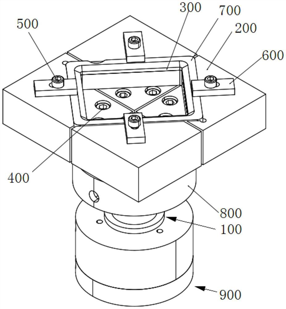
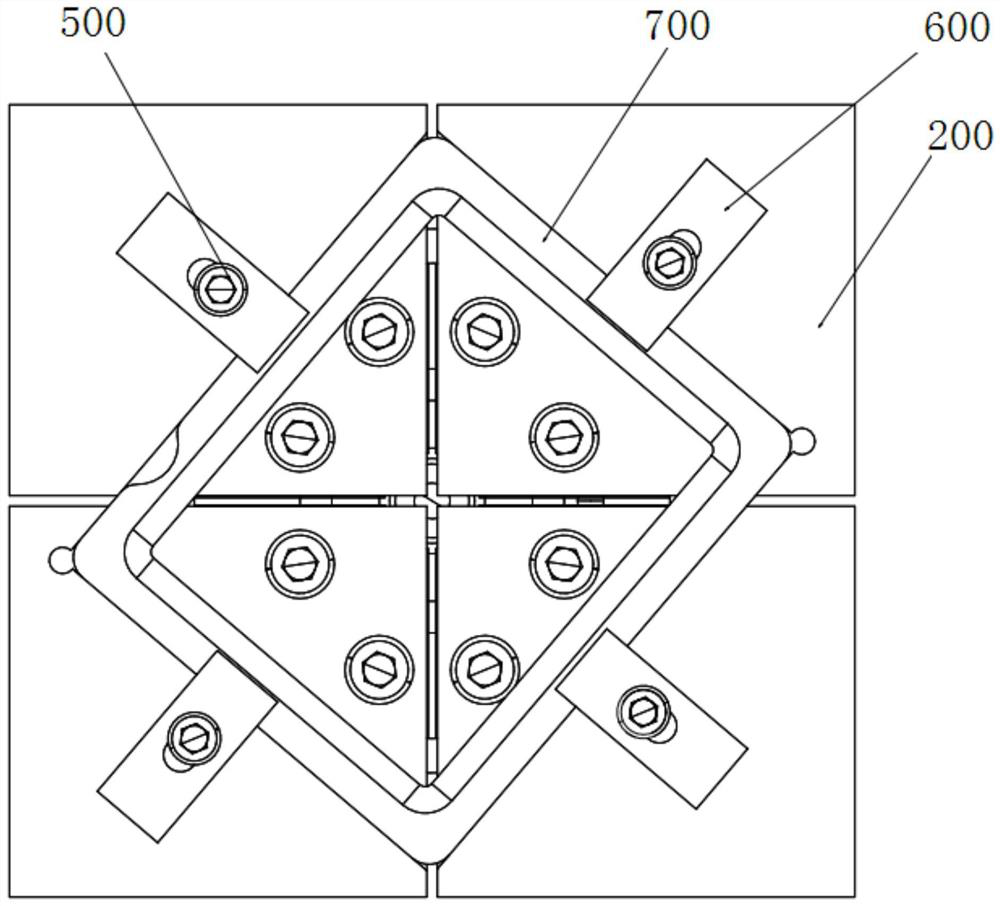
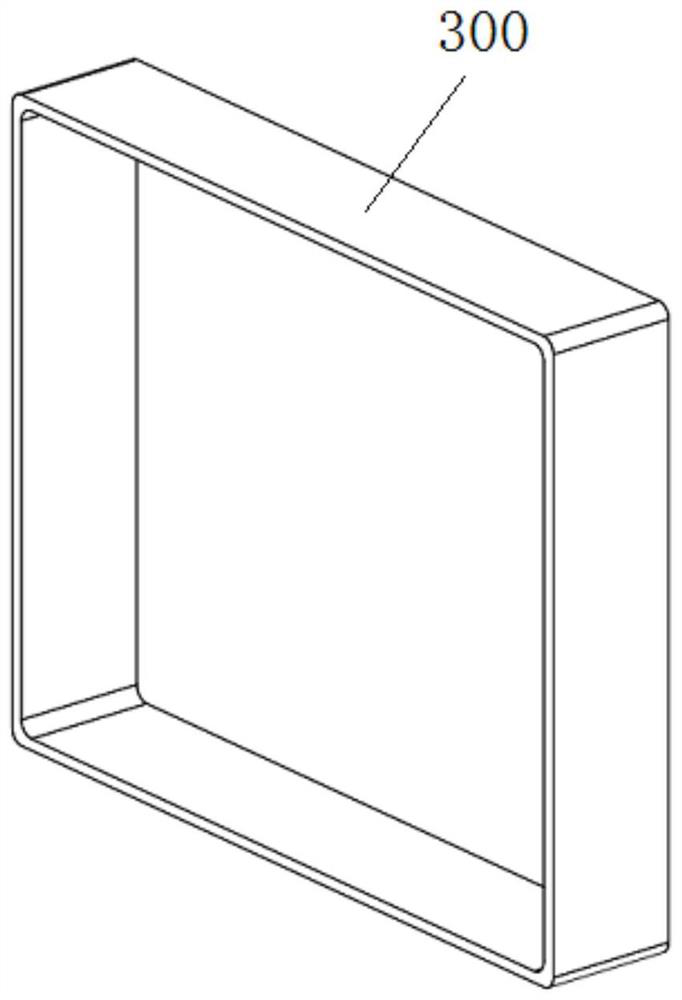
[0036] Such as Figure 1-Figure 10 as shown, figure 1 A schematic structural view showing a clamping fixture in a preferred embodiment of the present invention; figure 2 show figure 1 The schematic diagram of the structure of the clamping fixture shown in the other direction; image 3 A structural schematic diagram of a workpiece is shown; Figure 4 show figure 1 The schematic diagram of the connection structure of the four-petal fixture and the power structure of the clamping fixture shown; Figure 5 show figure 1 The installation diagram of the positioning block, four-petal fixture and power structure of the clamping fixture shown; Figure...


PUM


Abstract

A clamping fixture comprises a four-piece fixture, four positioning blocks and a chuck sleeve. The four-piece clamp is provided with a supporting sleeve, and two first chucks and two second chucks which are elastically arranged on the supporting sleeve. The outer side faces of the first chucks and the outer side faces of the second chucks are the same in shape and size. The top of the inner ring face of the chuck sleeve is in a circular-truncated-cone side face shape. The bottoms of the outer side faces of the first chucks and the bottoms of the outer side faces of the second chucks are curved surfaces matched with the top of the inner ring surface of the chuck sleeve. The top surfaces of the two first chucks and the top surfaces of the two second chucks are flush and are respectively provided with the positioning blocks. The four positioning blocks are used for limiting a workpiece in a matched mode. The two first chucks and the two second chucks are concentrated together and are arranged in the chuck sleeve in a penetrating manner. The clamping fixture further comprises a power structure which is connected with the chuck sleeve and used for driving the chuck sleeve to axially move relative to the first chucks and the second chucks. The clamping fixture is accurate in positioning, high in clamping stability and high in repeated positioning accuracy.

Description

technical field [0001] The invention relates to the field of mechanical tools, in particular to a clamping fixture. Background technique [0002] Thin-walled ring frame parts, as load-bearing supporting structures or guiding structures, are widely used in the fields of automobiles, aerospace and other fields, and mainly play the roles of supporting, guiding and positioning, and reducing weight. The critical surfaces of this type of part are the inner and outer ring surfaces. Considering the structural performance of the parts, the coaxiality and symmetry of the surface of the inner ring and the outer ring are usually required; at the same time, according to the assembly requirements and the use environment, the surface roughness of the parts and the surface without scratches are also proposed. Wait for the request. [0003] Thin-walled ring frame parts have the characteristics of small rigidity, thin thickness, easy deformation, and high precision. During the processing pr...

Claims


Application Information

Patent Timeline
IPC IPC(8): B25B11/00
CPCB25B11/00
Inventor 王传鹏刘英才张金林赵晓飞蔡煜东胡国强郑延吉
Owner SHENZHEN FLYTA TECH DEV
Why Eureka
Try Eureka