
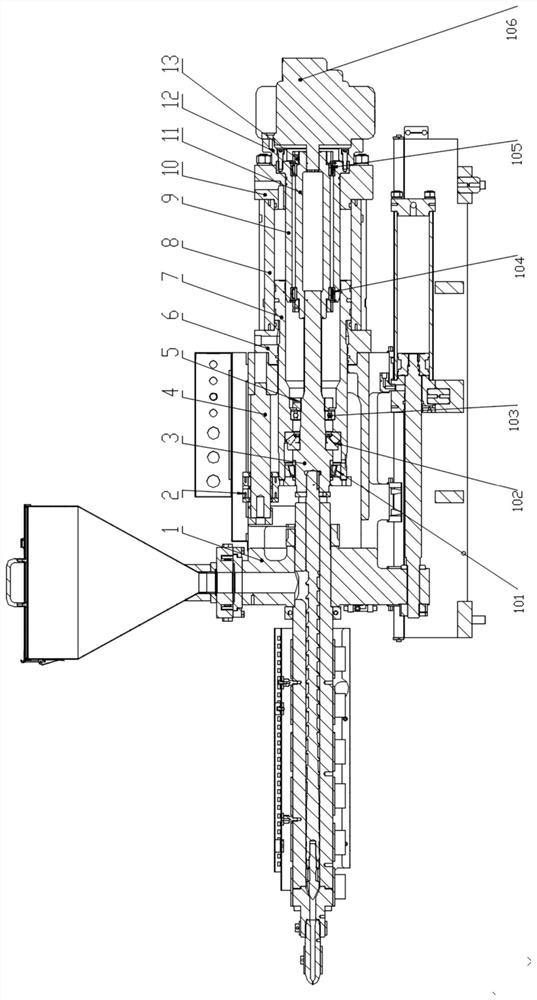
Single-oil-cylinder glue injection mechanism

A single cylinder, injection technology, applied in the field of injection molding, can solve problems such as internal leakage, pressure instability, etc.

Pending Publication Date: 2022-01-28
BORCH MACHINERY
View PDF0 Cites 0 Cited by
  • Summary
  • Abstract
  • Description
  • Claims
  • Application Information

AI Technical Summary

Problems solved by technology

[0005] In order to overcome the deficiencies of the prior art, one of the objectives of the present invention is to provide a single cylinder injection mechanism, which can solve the problems of internal leakage and pressure instability

Method used


Image

  • Single-oil-cylinder glue injection mechanism

Examples


Embodiment Construction

[0022] Below, the present invention will be further described in conjunction with the accompanying drawings and specific implementation methods. It should be noted that, under the premise of not conflicting, the various embodiments described below or the technical features can be combined arbitrarily to form new embodiments. .

[0023] It should be noted that when a component is said to be "fixed" to another component, it can be directly on the other component or there can also be an intervening component. When a component is said to be "connected" to another component, it may be directly connected to the other component or there may be intervening components at the same time. When a component is said to be "set on" another component, it may be set directly on the other component or there may be an intervening component at the same time. The terms "vertical," "horizontal," "left," "right," and similar expressions are used herein for purposes of illustration only.

[0024] Un...


PUM


Abstract

The invention discloses a single-oil-cylinder glue injection mechanism. A locking nut is mounted on a transmission shaft and locks a single-row tapered roller bearing, a thrust self-aligning roller bearing and a deep groove ball bearing; an inner ring and an outer ring of the roller bearing are respectively arranged on a transition sleeve and a spline transition sleeve in a hot pressing mode and locked through a transition sleeve locking nut, the whole assembly reciprocates along the inner wall of a rubber injection oil cylinder body, a rubber injection head plate is installed in the front portion of the transmission shaft, a rubber injection oil cylinder front cover and a rubber injection oil cylinder rear cover are respectively installed at two ends of the rubber injection oil cylinder body, the glue injection piston rod is slidably installed on the glue injection oil cylinder body, and the hydraulic motor is fixedly connected with the transition sleeve through a hydraulic motor flange. The transmission shaft is connected with the spline transition sleeve through an involute spline, it is ensured that the transmission shaft and the spline transition sleeve are concentric in the reciprocating motion process, it can be ensured that there is no swing in the glue melting action or rotating action process, cylinder mixing and internal leakage between the two cylinders caused by garland on the inner wall of the glue injection oil cylinder body can be avoided, and the problem of unstable pressure is solved.

Description

technical field [0001] The invention relates to the field of injection molding, in particular to a single-cylinder glue injection mechanism. Background technique [0002] At present, injection molding machines are also known as injection molding machines or injection machines. It is the main molding equipment for making thermoplastics or thermosetting plastics into various shapes of plastic products using plastic molding molds. Divided into vertical, horizontal, all-electric. The injection molding machine heats the plastic, applies high pressure to the molten plastic, and makes it shoot out to fill the mold cavity. [0003] However, the existing injection unit has the following disadvantages: [0004] Due to the rotation and reciprocating linear motion of the injection molding units on the market, internal leakage and unstable pressure are caused, the injection accuracy is insufficient, and the cost is high. Contents of the invention [0005] In order to overcome the d...

Claims


Application Information

Patent Timeline
Patent Type & Authority Applications(China)
IPC IPC(8): B29C45/58
CPCB29C45/58
Inventor 王书萍孙晓波袁中华杜呈表周清华吴小廷刘媛
Owner BORCH MACHINERY
Learn More