Water supply and drainage equipment for hydraulic engineering construction

A water conservancy project, water supply and drainage technology, applied in the direction of water conservancy engineering equipment, water conservancy engineering, mechanical equipment, etc., can solve the problems of drainage tank congestion, drainage tank flow reduction, etc., and achieve the effect of safe discharge

Pending Publication Date: 2022-01-28
福建省华舜水利水电工程有限公司
View PDF0 Cites 0 Cited by
  • Summary
  • Abstract
  • Description
  • Claims
  • Application Information

AI Technical Summary

Problems solved by technology

[0003] The existing water supply and drainage equipment for water conservancy construction mainly has the following shortcomings: when the water pump pumps out the water flow under the foundation, the water flow carries gravel, and when it is discharged, because the drainage groove is in the shape of a cone, the gravel is in the water. Under the impact of the impact, it is stuck in the drainage groove, causing the drainage groove to be congested by the accumulation of gravel, causing the flow rate of the drainage groove to become smaller when draining

Method used


Image

  • Water supply and drainage equipment for hydraulic engineering construction
  • Water supply and drainage equipment for hydraulic engineering construction
  • Water supply and drainage equipment for hydraulic engineering construction

Examples


Embodiment 1

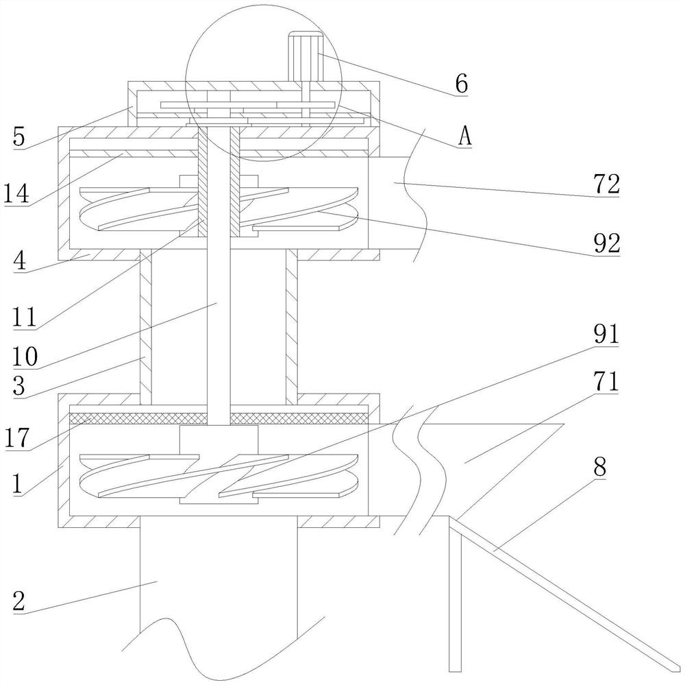
[0021] Such as Figure 1-3 As shown, a kind of water supply and drainage equipment for water conservancy construction proposed by the present invention includes a water suction frame 1, water pipe 2, connecting pipe 3, b water suction frame 4, a drain pipe 71, b drain pipe 72, a impeller 91, b Impeller 92, a rotating column 10, b rotating column 11 and filter screen 17;

[0022] The two ends of the connecting pipe 3 communicate with the water absorption frame a and the water absorption frame b respectively, and the b water absorption frame 4 is located above the a water absorption frame 1; the water pipe 2 is arranged at the lower end of the a water absorption frame 1; On the frame 1, the b drain pipe 72 is arranged on the b water absorption frame 4; the b rotating column 11 is arranged on the b water absorbing frame 4, and the b impeller 92 is arranged on the b rotating column 11; the b rotating column 11 is a hollow circular tubular structure; a The rotation column 10 is in...

Embodiment 2

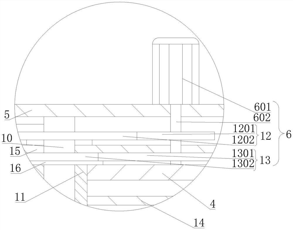
[0025] Such as Figure 1-3 As shown, the present invention proposes a water supply and drainage equipment for water conservancy construction. Compared with Embodiment 1, the driving mechanism 6 in this embodiment includes a driving motor 601, a rotating shaft 602, a deceleration transmission mechanism 12 and a speed-up transmission mechanism 13 ; The b water-absorbing frame 4 is provided with mounting frame 5; Driving motor 601 is arranged on mounting frame 5, and the output end of driving motor 601 is connected with rotating shaft 602; Above; the output end of the deceleration transmission mechanism 12 is connected to the a rotating column 10; the output end of the speed increasing transmission mechanism 13 is connected to the b rotating column 11.

[0026] In this embodiment, the driving motor 601 drives the rotating shaft 602 to rotate, so that the rotating speed of the rotating shaft 602 is constant, the a rotating column 10 is driven to rotate through the deceleration tra...

Embodiment 3

[0028] Such as Figure 1-3 As shown, the present invention proposes a water supply and drainage equipment for water conservancy construction. Compared with Embodiment 1 or Embodiment 2, the reduction transmission mechanism 12 in this embodiment includes a driving gear 1201 and a driven gear 1202; The gear 1201 is arranged on the rotating shaft 602; the a driven gear 1202 is arranged on the a rotating column 10, and the a driving gear 1201 is engaged with the a driven gear 1202; the number of teeth of the a driving gear 1201 is smaller than that of the a driven gear 1202. Speed-up transmission mechanism 13 comprises b driving gear 1301 and b driven gear 1302; b driving gear 1301 is arranged on the rotating shaft 602, b driven gear 1302 is arranged on b rotating column 11; b driving gear 1301 and b driven gear 1302 meshing connection; the number of teeth of a driving gear 1201 is equal to the number of teeth of b driven gear 1302; the number of teeth of a driven gear 1202 is equ...


PUM


Abstract

The invention relates to water supply and drainage equipment for hydraulic engineering construction, and belongs to the technical field of sewage treatment. In order to solve the problem that gravel blocks a drainage groove, the following technical schemes are provided: the equipment comprises a water absorption frame a, a water pipe, a connecting pipe, a water absorption frame b, a drainage pipe a, a drainage pipe b, an impeller a, an impeller b, a rotating column a, a rotating column b and a filter screen; two ends of the connecting pipe are respectively communicated with the water absorption frame a and the water absorption frame b; the water pipe is arranged at the lower end of the water absorption frame a; the drainage pipe a is arranged on the water absorption frame a, and the drainage pipe b is arranged on the water absorption frame b; the rotating column b is arranged on the water absorption frame b, and the impeller b is arranged on the rotating column b; the rotating column a is rotationally arranged in the rotating column b, and the impeller a is arranged on the rotating column a; a driving mechanism for driving the rotating column a and the rotating column b to rotate is arranged on the water absorption frame b, and the rotating speed of the rotating column a is smaller than that of the rotating column b; and the filter screen is arranged in the water absorption frame a. The equipment can separate broken stones.

Description

technical field [0001] The invention relates to the technical field of sewage treatment, in particular to water supply and drainage equipment for water conservancy construction. Background technique [0002] Water conservancy project is a kind of engineering facility used to allocate and control water resources. When building a dam of a water conservancy project, it is necessary to drain the water in the foundation hole through water supply and drainage equipment, and then construct steel bars and concrete to make it The foundation can be fixedly supported for water storage control and management. [0003] The existing water supply and drainage equipment for water conservancy construction mainly has the following shortcomings: when the water pump pumps out the water flow under the foundation, the water flow carries gravel, and when it is discharged, because the drainage groove is in the shape of a cone, the gravel is in the water. Under the impact of the impact, it is press...

Claims


Application Information

Patent Timeline
Patent Type & Authority Applications(China)
IPC IPC(8): F04D7/04F04D13/06F04D13/14F04D29/42F04D29/70E02D19/06E02B1/00F16H57/02F16H57/023
CPCF04D7/04F04D13/06F04D13/14F04D29/4293F04D29/708E02D19/06E02B1/00F16H57/02F16H57/023F16H2057/02034F16H2057/02039
Inventor 吴丽榕凌朗张仁旭陈建锋
Owner 福建省华舜水利水电工程有限公司
Why Eureka
Try Eureka