Multi-degree-of-freedom adjustable optical damping platform

A degree of freedom and optical technology, applied in the field of optical platforms, can solve problems such as complex adjustment process, inapplicable optical system usage, poor stability of the platform, etc.

Active Publication Date: 2022-01-28
INST OF APPLIED ELECTRONICS CHINA ACAD OF ENG PHYSICS
View PDF18 Cites 0 Cited by
  • Summary
  • Abstract
  • Description
  • Claims
  • Application Information

AI Technical Summary

Problems solved by technology

[0002] The existing optical platforms commonly used for optical components and optical path layout and installation are usually installed on the air bearing vibration reduction system, and the air bearing vibration reduction system is usually designed for fixed vibration reduction and vibration isolation frequency according to the vibration excitation spectrum characteristics of the use environment , each support point of the air bearing support and vibration reduction system has a certain real-time leveling function through air pressure adjustment, and is mostly suitable for a single stand-alone use; when the number of optical components is large, the coupling optical path is complex, the transmission distance is long, and multiple platforms are required When in use, the adjustment process is more complicated, and the relative stability between platforms is poor
In addition, the optical platform in the prior art is not suitable for the use of complex optical systems that require frequent changes in installation and use locations where the vibration excitation spectrum is uncertain, and the long-term relative stability of multiple platforms is poor when used jointly

Method used


Image

  • Multi-degree-of-freedom adjustable optical damping platform
  • Multi-degree-of-freedom adjustable optical damping platform

Examples


Embodiment Construction

[0033] In order to understand the above-mentioned purpose, features and advantages of the present invention more clearly, the present invention will be further described in detail below in conjunction with the accompanying drawings and specific embodiments. It should be noted that, in the case of no conflict, the embodiments of the present application and the features in the embodiments can be combined with each other.

[0034] In the following description, many specific details are set forth in order to fully understand the present invention. However, the present invention can also be implemented in other ways than described here. Therefore, the protection scope of the present invention is not limited by the specific implementation disclosed below. Example limitations.

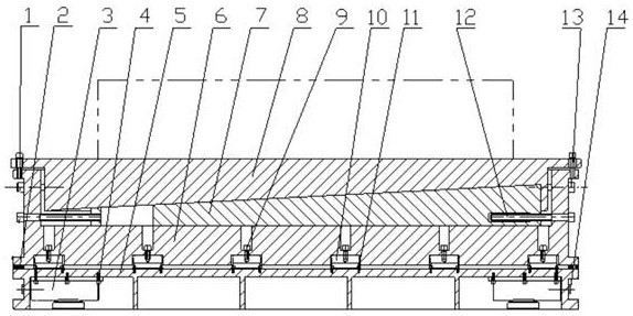
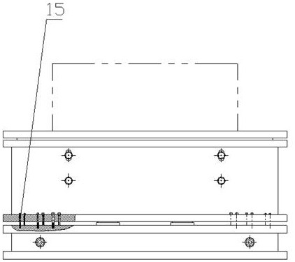
[0035] Refer below Figure 1 to Figure 2 A multi-degree-of-freedom adjustable optical vibration reduction platform provided according to some embodiments of the present invention will be described.

[0036]...


PUM


Abstract

The invention provides a multi-degree-of-freedom adjustable optical damping platform. The multi-degree-of-freedom adjustable optical damping platform comprises a mounting base, a middle body connected with the mounting base through a shock absorber, a wedge iron type adjusting body connected to the middle body in a sliding manner, a worktable arranged on the middle body, and having the lower end surface matched with and contacted with the upper end surface of the wedge iron type adjusting body in shape, a lifting adjusting assembly, and a horizontal adjusting assembly. The multi-degree-of-freedom adjustable optical damping platform can be used independently, can also be used in a combined mode, and can be suitable for complex optical path coupling alignment and installation positioning occasions with high precision requirements and indefinite or frequently-changed use environment vibration excitation frequency spectrum characteristics. The platform is especially suitable for optical path coupling alignment and adjustment positioning of a complex optical system which is large in number of optical elements, complex in coupling optical path and long in transmission distance, needs a plurality of optical platforms to be combined for use, frequently changes installation and use places and is large in environmental vibration excitation spectrum difference.

Description

technical field [0001] The invention relates to the technical field of optical platforms, in particular to an adjustable multi-degree-of-freedom optical vibration reduction platform. Background technique [0002] The existing optical platforms commonly used for optical components and optical path layout and installation are usually installed on the air bearing vibration reduction system, and the air bearing vibration reduction system is usually designed for fixed vibration reduction and vibration isolation frequency according to the vibration excitation spectrum characteristics of the use environment , each support point of the air bearing support and vibration reduction system has a certain real-time leveling function through air pressure adjustment, and is mostly suitable for a single stand-alone use; when the number of optical components is large, the coupling optical path is complex, the transmission distance is long, and multiple platforms are required When in use, the ...

Claims


Application Information

Patent Timeline
Patent Type & Authority Applications(China)
IPC IPC(8): F16M11/04F16M11/18F16M11/16F16F15/02
CPCF16M11/045F16M11/046F16M11/18F16M11/16F16F15/02F16F2230/0005
Inventor 鲜玉强刘雪婷崔鼎陈永亮张伟周文超严从林荆建瑛李才阳张林陈涛
Owner INST OF APPLIED ELECTRONICS CHINA ACAD OF ENG PHYSICS
Why Eureka
Try Eureka