Reactive compensation equipment switching method and device

A compensation equipment, switching technology, applied in the direction of reactive power compensation, reactive power adjustment/elimination/compensation, circuit devices, etc., can solve the problems of switch refusal to jump, tripping, fault tripping, lack of reactive power compensation equipment rotation strategy, etc. , to avoid failures and improve safety

Pending Publication Date: 2022-01-28
GUANGDONG POWER GRID CO LTD +1
View PDF0 Cites 2 Cited by
  • Summary
  • Abstract
  • Description
  • Claims
  • Application Information

AI Technical Summary

Problems solved by technology

However, the existing control strategy lacks a rotation strategy for reactive power compensation equipment, and it is easy to cause some reactive power compensation equipment to run for a long time, resulting in failure of reactive power compensation equipment, ranging from tripping due to faults, to explosions and tripping when the switch refuses to move. and other issues, affecting the safe operation of the power grid system

Method used


Image

  • Reactive compensation equipment switching method and device
  • Reactive compensation equipment switching method and device
  • Reactive compensation equipment switching method and device

Examples


Embodiment Construction

[0032] The present invention will be further described in detail below in conjunction with the accompanying drawings and embodiments. It should be understood that the specific embodiments described here are only used to explain the present invention, but not to limit the present invention. In addition, it should be noted that, for the convenience of description, only some structures related to the present invention are shown in the drawings but not all structures.

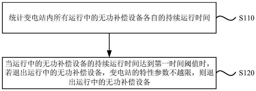
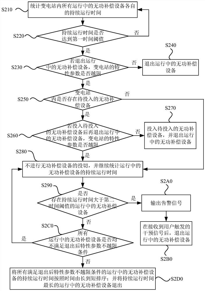
[0033] The embodiment of the present invention provides a reactive power compensation equipment switching method, which can be realized based on the reactive power compensation equipment switching device, the method can be used as a supplement to the reactive power dispatching strategy in the power grid system, and is applicable to substations of all levels reactive power adjustment requirements. figure 1 It is a schematic flowchart of a reactive power compensation equipment switching method provided by an embodim...


PUM


Abstract

The invention discloses a reactive compensation equipment switching method and device. The method comprises the following steps: counting respective continuous operation time of all reactive power compensation equipment in operation in a transformer substation; and when the continuous operation time of the reactive power compensation equipment in operation reaches a first time threshold value, if the reactive power compensation equipment in operation is quitted and the characteristic parameters of the transformer substation do not exceed the limit, quitting the reactive power compensation equipment in operation. According to the embodiment of the invention, alternate operation of the reactive compensation equipment can be realized, faults caused by long-time operation of the reactive compensation equipment are avoided, and the operation safety of a power grid system is improved.

Description

technical field [0001] Embodiments of the present invention relate to the technical field of power systems, and in particular to a method and device for switching reactive power compensation equipment. Background technique [0002] In the power grid system, in order to maintain reactive power balance and voltage stability, each substation is equipped with a certain number of reactive power compensation equipment. Existing power grid system scheduling is realized through the AVC system (Automatic Voltage Control, automatic voltage control system), specifically through the scheduling automation SCADA system (Supervisory Control And Data Acquisition, data acquisition and monitoring control system) to collect the busbars of each substation and power plant Centralized monitoring, analysis and calculation of key measurement data such as voltage, and automatic switching of reactive power compensation equipment according to demand. However, the existing control strategy lacks a rot...

Claims


Application Information

Patent Timeline
Patent Type & Authority Applications(China)
IPC IPC(8): H02J3/18
CPCH02J3/1821Y02E40/30
Inventor 罗松林陈守滨刘宏李敬光陈佳辉杨阳刘树安
Owner GUANGDONG POWER GRID CO LTD
Why Eureka
Try Eureka