Rotary imaging system, plant imager, animal imager and animal and plant imager

An imaging system and a rotary technology, applied in the direction of instruments, scientific instruments, chemiluminescence/bioluminescence, etc., can solve the problems of image information deviation, increase system cost, sample sliding, etc., and achieve small space, compact structure, and reduced quantity Effect

Pending Publication Date: 2022-02-01
SHANGHAI CLINX SCI INSTR
View PDF0 Cites 5 Cited by
  • Summary
  • Abstract
  • Description
  • Claims
  • Application Information

AI Technical Summary

Problems solved by technology

However, it is easy to cause the sample to slip during the actual movement of the sample stage, which makes the final image information deviate from the initial expected image; in addition, the use of multiple cameras will greatly increase the system cost

Method used


Image

  • Rotary imaging system, plant imager, animal imager and animal and plant imager
  • Rotary imaging system, plant imager, animal imager and animal and plant imager
  • Rotary imaging system, plant imager, animal imager and animal and plant imager

Examples


Embodiment Construction

[0168] The present invention is further illustrated below by means of examples, but the present invention is not limited to the scope of the following examples.

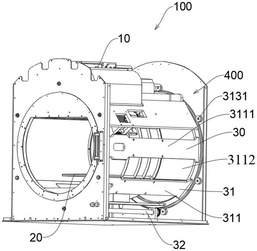
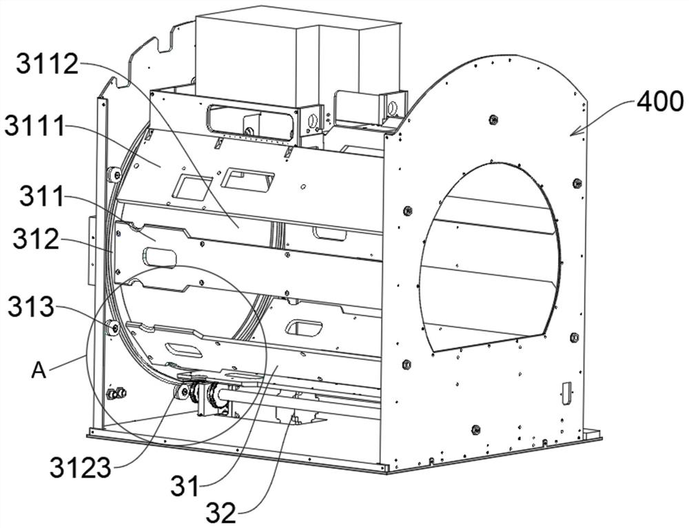
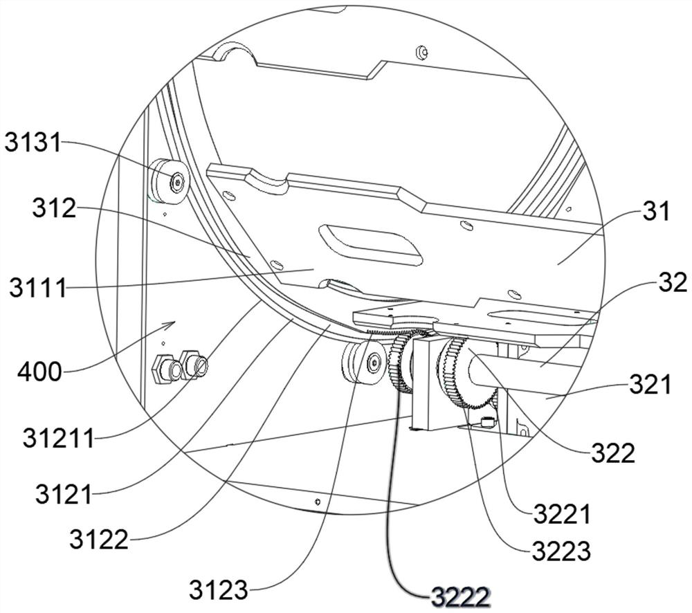
[0169] An embodiment of the present invention provides a rotary imaging system 100 for imaging a sample 200 . The imaging system 100 of the embodiment of the present invention is used in an imager 1000 , and the imaging system 100 is installed in a casing 400 of the imager 1000 . For ease of understanding, the technical connection between the imaging system 100 and the casing 400 will be introduced accordingly in the process of explaining the structure of the imaging system 100 below.

[0170] Please refer to figure 1 to understand. The imaging system 100 of the embodiment of the present invention includes a sample stage unit 20, a camera unit 10, and a rotation unit 30; the sample stage unit 20 is used to carry the sample 200; the camera unit 10 is used to image the sample 200; The accommodating cavity 3112 of th...


PUM


Abstract

The invention discloses a rotary imaging system, a plant imager, an animal imager and an animal and plant imager, and belongs to the technical field of living body sample imaging. In the invention, the plant imager, the animal imager and the animal and plant imager respectively comprise a rotary imaging system, and each rotary imaging system comprises a sample stage unit, a camera unit and a rotating unit; the sample table unit is used for bearing samples; the camera unit is used for imaging the sample; and the rotating unit comprises a containing cavity containing the sample table unit, and the rotating unit is used for driving the camera unit to rotate relative to the sample table unit and controlling the camera unit to be static relative to the sample table unit. Through the rotary imaging system, powerful data support is provided for subsequent image reconstruction and image fusion. The number of cameras required for imaging different positions of the sample is also reduced.

Description

technical field [0001] The invention relates to the technical field of living sample imaging, in particular to a rotary imaging system, a plant imager, an animal imager and an animal and plant imager. Background technique [0002] In vivo imaging technology uses imaging methods to quickly observe the optical signals of the living body non-invasively, and conduct qualitative and quantitative research on the biological processes in the living body at the cellular and molecular levels. The development of assessment and treatment has had a major contribution. [0003] In the existing in vivo imaging technology, the sample stage carries the sample, and the sample is imaged through multiple cameras, and by adjusting the relative position relationship between the sample stage and the camera, the sample at different positions is imaged, in order to further carry out the two-dimensional reconstruction of the image. Image information can be provided by the operation of image structur...

Claims


Application Information

Patent Timeline
Patent Type & Authority Applications(China)
IPC IPC(8): A61B5/00A61B6/00A61B6/04G01N21/64G01N21/76G01N21/84G01N23/04G01N23/083
CPCA61B6/04A61B6/42A61B5/0071A61B5/0077A61B6/4476G01N21/84G01N21/6456G01N21/763G01N23/04G01N23/083A61B5/704A61B2503/40A61B5/00G01N2021/6482G01N2021/8466G01N2021/6419G01N21/01G02B26/0816G02B7/18G02B7/1815A61B5/0035A61B5/0059A61B6/0407A61B6/4417A61B6/508G01N2223/3306
Inventor 蔡荣伟陈雄群王慧明储德保高捷
Owner SHANGHAI CLINX SCI INSTR
Why Eureka
Try Eureka