Petroleum filter screen forming device

A forming device and filter net technology, which is applied in the direction of forming tools, feeding devices, positioning devices, etc., can solve the problems of potential safety hazards, damage to forming plates on equipment, and low utilization rate of forming plates, so as to reduce the degree of damage and improve work efficiency. efficiency effect

Inactive Publication Date: 2022-02-01
朱娟
View PDF0 Cites 0 Cited by
  • Summary
  • Abstract
  • Description
  • Claims
  • Application Information

AI Technical Summary

Problems solved by technology

[0005] In order to overcome the disadvantages that the traditional filter forming equipment presses the filter plate manually, there are potential safety hazards, and the forming equipment works for a long time, which easily damages the forming plate on the equipment, resulting in a low utilization rate of the forming plate, the present invention The technical problem is: to provide a petroleum filter forming device which has a cooling function and can automatically compress the filter plate

Method used


Image

  • Petroleum filter screen forming device
  • Petroleum filter screen forming device
  • Petroleum filter screen forming device

Examples


Embodiment 1

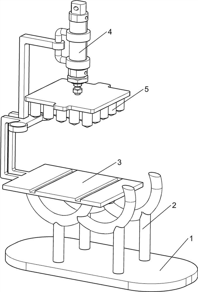
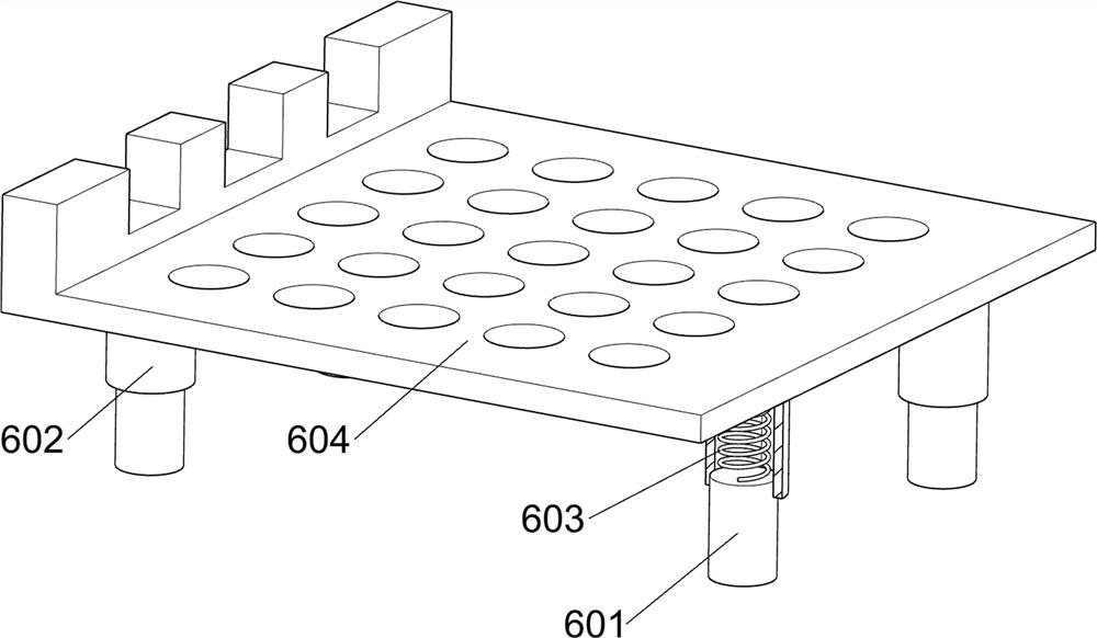
[0027] A petroleum filter forming device, such as figure 1 , figure 2 , image 3 and Figure 4 As shown, it includes a base 1, a bracket 2, a workbench 3, a cylinder 4, a forming block 5, a placement component 6 and a pressing component 7. The top of the base 1 is provided with a bracket 2, and the left side of the top of the bracket 2 is provided with a workbench 3. The top left side of the workbench 3 is provided with a cylinder 4, the piston rod of the cylinder 4 is provided with a forming block 5, the top of the workbench 3 is provided with a placement assembly 6, and the left side of the workbench 3 top is provided with a compression assembly 7.

[0028] When people need to make a filter net, people put the filter plate on the placement component 6, and then start the cylinder 4, and under the action of the piston rod of the cylinder 4, the forming block 5 is driven to move down to contact the compression component 7, and the compression component 7 is pressed. Under ...

Embodiment 2

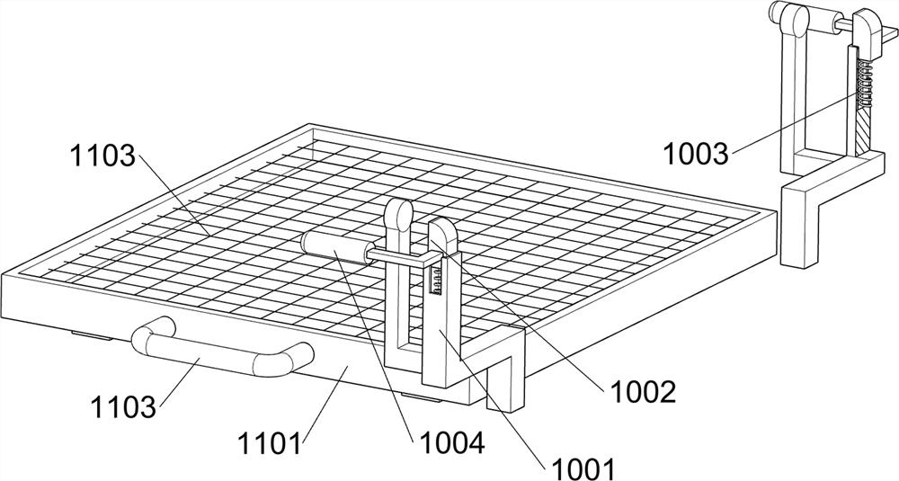
[0034] On the basis of Example 1, such as Figure 5 , Figure 6 and Figure 7 As shown, it also includes a pushing assembly 8, and the pushing assembly 8 includes a material frame 801, a third guide rod 802, a slider 803, a fourth spring 804, a special-shaped frame 805, a handle 806 and a material guide plate 807, and the top of the bracket 2 The right side is provided with material guide plate 807, is provided with material frame 801 between material guide plate 807 upper inner sides, and material frame 801 right side front and rear sides are provided with the 3rd guide bar 802, all sliding type is provided with on the 3rd guide bar 802. Block 803, the fourth spring 804 is arranged between the slide block 803 and the material frame 801, the fourth spring 804 is set on the third guide rod 802, and the inside of the bottom of the material frame 801 is slidably provided with a special-shaped frame 805, and the slide block 803 The inner side is connected with the special-shaped f...


PUM


Abstract

The invention relates to a forming device, in particular to a petroleum filter screen forming device, and aims to provide the petroleum filter screen forming device which has a cooling function and can automatically press a filter plate. According to the technical scheme, the petroleum filter screen forming device comprises a base and a support arranged at the top of the base; a workbench arranged at one side of the top of the support; a cylinder arranged at the upper part of one side of the workbench; a forming block arranged on a piston rod of the air cylinder; a placing assembly arranged at the top of the workbench; and a pressing assembly is arranged at one side of the top of the workbench. Under the action of the piston rod of the air cylinder, the forming block is driven to move downwards to make contact with the pressing assembly, a filter plate is pressed under the effect of the pressing assembly, the forming block conveniently punches the filter plate into a filter screen shape, and the effect of pressing the filter plate is achieved.

Description

technical field [0001] The invention relates to a forming device, in particular to a forming device for petroleum filter nets. Background technique [0002] The filter screen has the properties of acid resistance, alkali resistance, wear resistance, etc. It is mainly used in air conditioners, purifiers, range hoods, chemicals, food, pharmaceuticals, etc., and is suitable for filtration in various industries. [0003] Due to the wide range of use of filters, people's requirements for the output of filters are also increasing. At present, there are still some shortcomings in the traditional filter forming equipment. The traditional filter forming equipment is to manually press the filter plate. There are potential safety hazards, and the molding equipment works for a long time, and the equipment is prone to heat. When the molding equipment is constantly working, it is easy to damage the molding board on the equipment, resulting in a low utilization rate of the molding board, a...

Claims


Application Information

Patent Timeline
IPC IPC(8): B21D31/02B21D43/00B21D43/22B21D37/16
CPCB21D31/02B21D43/003B21D43/22B21D37/16
Inventor 朱娟
Owner 朱娟
Why Eureka
Try Eureka