Coiled material folding device

A folding device and coil technology, which is applied in the directions of winding strips, folding thin materials, transportation and packaging, etc., can solve the problems of high cost, inability to meet the automation level of production lines, low efficiency, etc., and achieve the effect of improving production efficiency.

Active Publication Date: 2022-02-01
BEIJING ZODNGOC AUTOMATIC TECH
View PDF8 Cites 0 Cited by
  • Summary
  • Abstract
  • Description
  • Claims
  • Application Information

AI Technical Summary

Problems solved by technology

Circular knife die-cutting machines are very common in the electronics industry, post-press die-cutting, mask production and other industries. In the production process of circular knife die-cutting machines, it is inevitable that coil products will eventually be sold in the form of sheets. In the past, coils had to be manually folded into the required quantity before packaging, which was low in efficiency and high in cost, and could not meet the automation level of the production line.

Method used


Image

  • Coiled material folding device
  • Coiled material folding device
  • Coiled material folding device

Examples


Embodiment 2

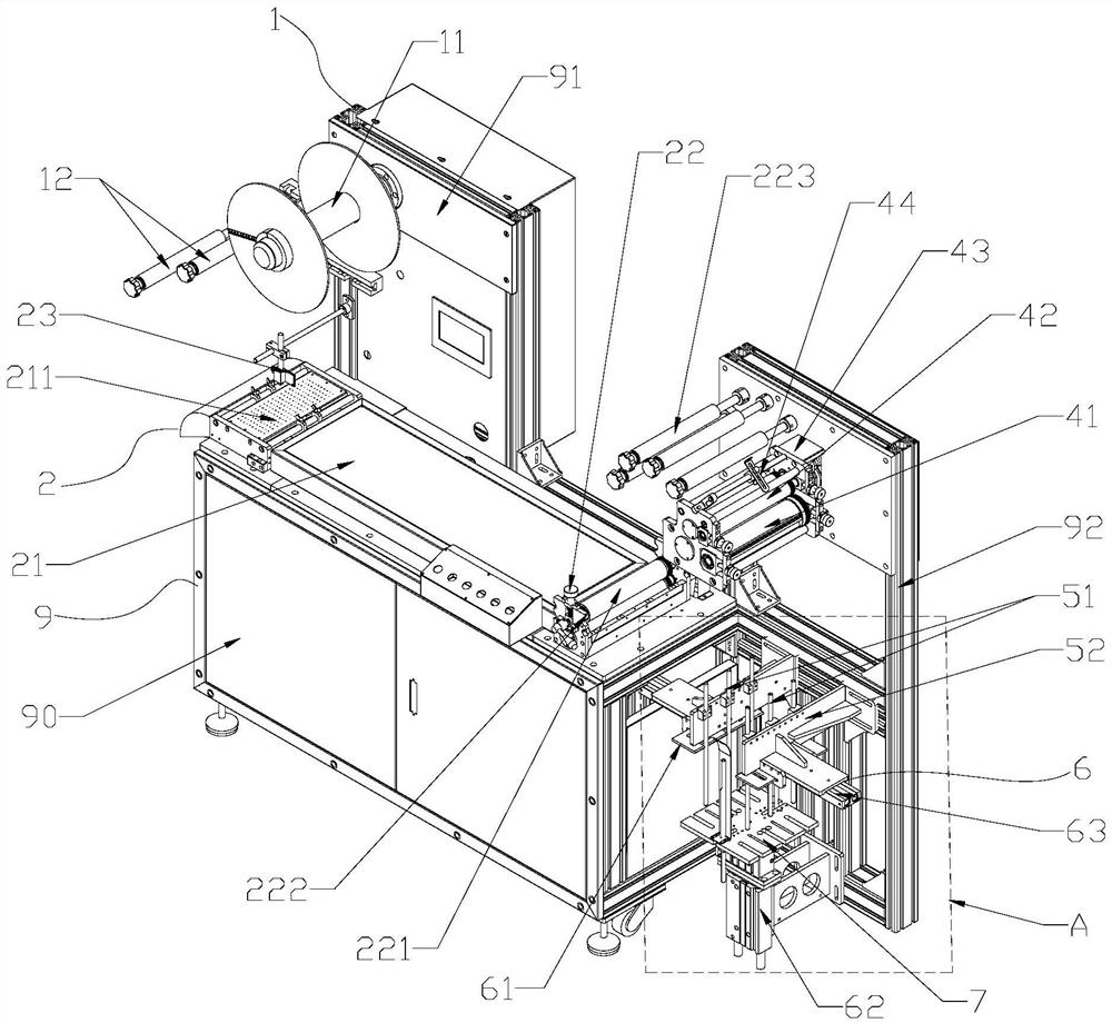
[0033] Such as Figure 4 In the crease mechanism shown, there are two die-cutting rollers 411, the two die-cutting rollers 411 are arranged in parallel, and the two die-cutting rollers 411 rotate in the same direction; the die-cutting rollers 411 include the first roller drum, the first roller shaft for installing the first roller, the outer circumferences of the two first rollers are tangent, the first U-shaped groove and the second U-shaped groove are provided on the first roller, and the first U-shaped groove is provided on the first roller. One U-shaped groove and the second U-shaped groove are arranged axially symmetrically, and one side of the first U-shaped groove and one side of the second U-shaped groove are all provided with a right-angle groove 4113, and the first U-shaped groove is filled with Rubber 4111, the second U-shaped groove is equipped with a cutter 4112. In this embodiment, the cutter head of the cutter 4112 protrudes from the outer circumference of the ...

Embodiment 3

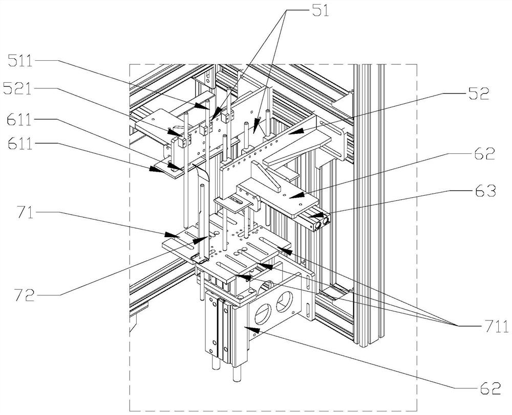
[0036] Described collection jig 7 comprises base plate 71, side plate 72, and the bottom of described base plate 71 is connected with the output end of cylinder 62, and described side plate 72 is installed on the front and back ends of base plate 71 top, and the both sides of described base plate 71 Each is provided with a third groove 711 for the guide rod 511 to pass through, and the third groove 711 is adapted to the shape of the guide rod 511 . The front and rear ends of the base plate 71 have a plurality of threaded holes, the side plate 72 is an L-shaped structure, and the bottom of the side plate 72 is connected with the threaded holes, so that when the coil size changes, the installation of the side plate 72 can be adjusted. The location is enough, and the collection of multi-size coils can be realized. At the same time, the design of the third groove 711, on the one hand, can cooperate with the side plate 72 to collect materials; When the coil size changes, the third...


PUM


Abstract

The invention relates to a coiled material folding device and belongs to the technical field of die cutting. The coiled material folding device comprises a discharging mechanism, a material belt conveying mechanism and a support, wherein the discharging mechanism and the material belt conveying mechanism are both installed on the support. The coiled material folding device further comprises a creasing mechanism, a folding mechanism and a collecting jig, wherein the material belt conveying mechanism is used for conveying a material belt on the discharging mechanism to the creasing mechanism, the creasing mechanism is used for bending the material belt conveyed by the material belt conveying mechanism to form a Z-shaped material belt, the folding mechanism is used for folding the Z-shaped material belt output by the creasing mechanism to the collecting jig, and the folding mechanism is located above the collecting jig. The coiled material folding, stacking and collecting functions are achieved, and the production efficiency can be effectively improved.

Description

technical field [0001] The invention relates to a roll material folding device, which belongs to the technical field of electrical component supporting equipment. Background technique [0002] With the large-scale use of circular knife die-cutting machines in all walks of life, the various mechanisms supporting it are also becoming more and more extensive. Circular knife die-cutting machines are very common in the electronics industry, post-press die-cutting, mask production and other industries. In the production process of circular knife die-cutting machines, it is inevitable that coil products will eventually be sold in the form of sheets. In the past, coils had to be manually folded into the required quantity before packaging, which was inefficient and costly, and could not meet the automation level of the production line. Contents of the invention [0003] In view of the above problems, the present invention proposes a coil folding device to realize the functions of ...

Claims


Application Information

Patent Timeline
Patent Type & Authority Applications(China)
IPC IPC(8): B65H16/04B65H16/00B65H20/02B65H26/00B65H23/038B65H45/16B65H45/28
CPCB65H16/04B65H16/00B65H20/02B65H26/00B65H23/038B65H45/16B65H45/28B65H2701/11332
Inventor 李振华鲁文桥叶振飞王英利朱超平
Owner BEIJING ZODNGOC AUTOMATIC TECH
Why Eureka
Try Eureka