Automatic wire barrow

A pay-off car, automatic technology, applied in the direction of conveying filamentous materials, cleaning methods and utensils, chemical instruments and methods, etc., can solve problems such as large space and occupation, and achieve improved cleaning effect, reduced space occupation, and improved convenience. degree of effect

Pending Publication Date: 2022-02-01
深圳市众汇智能科技有限公司
View PDF0 Cites 4 Cited by
  • Summary
  • Abstract
  • Description
  • Claims
  • Application Information

AI Technical Summary

Problems solved by technology

[0004] In view of the related technologies mentioned above, the inventor believes that there are the following defects: when the pay-off car needs to be transferred, the guide frame protrudes from the pay-off car and takes up a large space, so further improvement is needed

Method used


Image

  • Automatic wire barrow
  • Automatic wire barrow
  • Automatic wire barrow

Examples


Embodiment 1

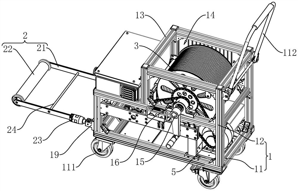
[0050] This embodiment discloses an automatic pay-off car, referring to figure 1 , figure 2 , including a frame body 1, a movable guide frame 2 hinged on one side of the frame body 1, a cable reel 3 rotatably connected to the frame body 1 for winding or unwinding cables, and a sliding connection on the cable seat 4 of the frame body 1.

[0051] The frame body 1 includes a bottom frame 11 , a pair of side frames 12 fixedly connected to both sides of the bottom frame 11 , and several connecting beams 13 fixedly connected between the two side frames 12 . The bottom of the bottom frame 11 is provided with moving wheels 111, and there are four moving wheels 111 which are respectively located at the four corners of the bottom of the bottom frame 11. Specifically, the moving wheels 111 are universal wheels, and one side of the side frame 12 is fixed A push rod 112 is connected to facilitate the staff to push the frame body 1 of the vehicle frame.

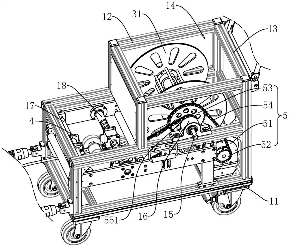
[0052] refer to figure 2 , ...

Embodiment 2

[0061] Embodiment 2: refer to Figure 13 , Figure 14 , the difference from Embodiment 1 is that the two guide support plates 21 are fixedly connected with a reinforcing plate 25, and the reinforcing plate 25 includes a mounting plate 251, a movable plate 252 slidingly connected to the mounting plate 251, and a movable plate 252 fixedly connected to the mounting plate 251 and the second elastic member 253 between the movable plate 252. The mounting plate 251 has an inner cavity for accommodating the movable plate 252 , and the mounting plate 251 has an outlet communicating with the inner cavity for the movable plate 252 to extend out. The second elastic member 253 is a spring. One end of the spring is fixedly connected to the inner wall of the inner cavity of the mounting plate 251 and the other end is fixedly connected to the movable plate 252 .

[0062] refer to Figure 14 , Figure 15A mounting sleeve 26 is fixedly connected between the two movable plates 252, and a cle...


PUM


Abstract

The invention relates to an automatic wire barrow. The automatic wire barrow comprises a frame body and a movable guide frame hinged to one side of the frame body, the frame body is provided with a hinge seat, a hinge groove is horizontally formed in one side of the hinge seat, a limiting clamping groove communicated with the hinge groove is vertically formed in the upper portion of the hinge seat, the movable guide frame comprises a pair of guide supporting plates, an inlet roller rotationally connected between the two guide supporting plates and a lifting and turning connecting seat fixedly connected to the guide supporting plates, the lifting and turning connecting seat is slidably connected with a lifting and turning shaft, the lifting and turning shaft is hinged to the inner wall of the hinge groove, a lifting and turning clamping sleeve is arranged on the lifting and turning connecting seat in a protruding mode, and a first elastic piece for forcing the lifting and overturning connecting seat to slide towards the direction close to the lifting and overturning shaft to enable the lifting and overturning clamping sleeve to be inserted into the limiting clamping groove is arranged between the lifting and overturning connecting seat and the lifting and overturning shaft. The automatic wire barrow has the effect of reducing the occupied space in the transportation process of the wire barrow.

Description

technical field [0001] The present application relates to the technical field of wire winding devices, in particular to an automatic wire pay-off vehicle. Background technique [0002] Pipelines are the lifeblood and meridians of cities. Pipelines are prone to aging or damage after long-term use. It is particularly important for the cleaning and detection of urban pipelines. Pipeline detection devices are widely used in municipal engineering underground pipeline detection, chimney detection, mine exploration small pipeline detection , Inner wall pipeline inspection, water investigation, pipeline detection work in the construction industry and other fields. [0003] The detection device is usually used to detect and detect the pipeline. The detection device includes a detection instrument, a pay-off car and a cable connected to the detection instrument and the pay-off car. Rewinding or unwinding of cables. One side of the pay-off vehicle is usually provided with a guide fra...

Claims


Application Information

Patent Timeline
Patent Type & Authority Applications(China)
IPC IPC(8): B65H75/42B65H75/44B65H54/28B65H61/00B08B1/02
CPCB65H75/425B65H75/4405B65H75/4486B65H54/2818B65H61/00B08B1/002B08B1/02B65H2701/34
Inventor 林开发姜涛
Owner 深圳市众汇智能科技有限公司
Why Eureka
Try Eureka