
Power-intelligently adjustable distributed LED power supply for railway compartment

A technology of LED power supply and intelligent adjustment, which is applied in the direction of circuit layout, light source, lighting device components, etc., can solve the problems of dangerous situations, excessive current output, and low practicability, so as to ensure safety, avoid short circuit, and facilitate Observe the effect of understanding

Pending Publication Date: 2022-02-01
嘉兴南湖学院
View PDF4 Cites 1 Cited by
  • Summary
  • Abstract
  • Description
  • Claims
  • Application Information

AI Technical Summary

Problems solved by technology

The utility model is provided with an internal interface on the side of the main body of the LED power supply away from the control button, and at the same time, a converter is provided inside the main body of the LED power supply, and at the same time, a cooling hole and a protection device are provided on the converter, which is suitable for use. This device cannot supply power to multiple sets of electrical appliances at the same time, and the practicability of the device is not high
[0006] 3. The comparative document CN210928406U discloses a LED power supply with an alarm function, "including an LED power supply shell and an alarm unit, and an LED power supply shell: an opening is provided on the top of the LED power supply shell, and the side of the upper surface of the rear end of the LED power supply shell is aligned with the The side of the front side of the cover plate is rotatably connected, and an alarm unit is fixed on the front side of the inner bottom surface of the LED power supply shell, and a battery is fixed on the rear side of the inner bottom surface of the LED power supply shell. The alarm unit: the alarm unit includes a digital power sensor, a first fixed Column, single-chip microcomputer, horn, first baffle plate and first through hole, the digital power sensor is fixed on the front side of the battery, the first fixing column is provided with two, respectively fixed on the front side of the inner bottom surface of the LED power supply shell, the first A horn is fixed on the front side of the fixed column, and a single-chip microcomputer is fixed on the upper surface of the first fixed column, and the first baffle is fixed on the front side inside the LED power supply shell. The LED power supply with alarm function has good heat dissipation, is easy to clean, and has Power alarm function", the device lacks a structure to control the output power, which can easily lead to excessive current output and dangerous situations

Method used


Image

  • Power-intelligently adjustable distributed LED power supply for railway compartment
  • Power-intelligently adjustable distributed LED power supply for railway compartment
  • Power-intelligently adjustable distributed LED power supply for railway compartment

Examples


Embodiment 1

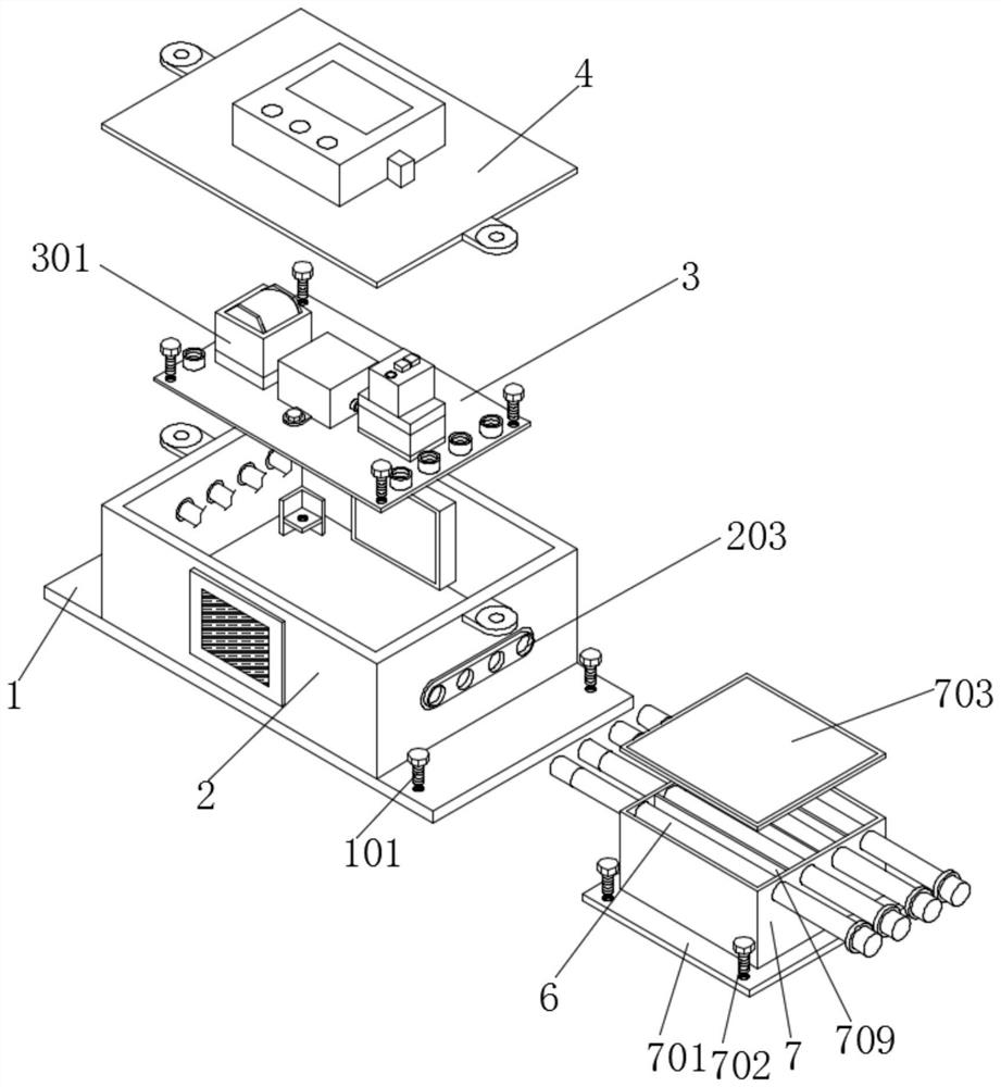
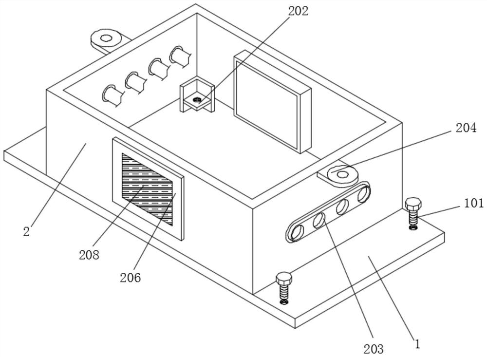
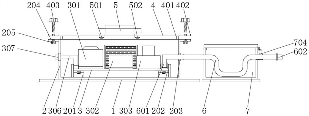
[0042] Embodiment 1 includes a mounting plate 1, first screws 101 are installed through the four corners of the mounting plate 1, and a housing 2 is installed on the top of the mounting plate 1, and the mounting plate 1 is installed on the car compartment through the first screws 101. Inside, the housing 2 is fixed by the mounting plate 1 to ensure the stability of the housing 2. A support frame 201 is installed on the inner bottom wall of the housing 2, and a support plate 202 is installed on the inner side of the support frame 201. The housing 2 pairs The inner support frame 201 is fixed to ensure that the support frame 201 remains stable, and the support plate 202 is fixed by the support frame 201, so that the support plate 202 is fixed to the upper substrate 3 through threads to ensure the stability of the substrate 3. Both sides of the housing 2 A connecting plate 204 is installed on the top, and an internal threaded hole 205 is installed on the inner side of the connectin...

Embodiment 2

[0044] Embodiment 2 includes a support plate 202, the top of the support plate 202 is installed with a base plate 3 through bolts, a transformer 301 is installed on the top of the base plate 3, and a rectifier 302 is installed on the top of the base plate 3 through bolts, and the rectifier 302 is located at the top of the transformer 301. On one side, the top of the base plate 3 is equipped with an overload protector 303 through bolts, and the overload protector 303 is located on the side of the rectifier 302 away from the transformer 301, and the top of the base plate 3 is equipped with four groups of connecting seats 304 arranged equidistantly, and the connecting seats 304 is located on the side of the transformer 301 away from the rectifier 302. The inner side of the connection base 304 is fitted with a transmission line 306, and one end of the transmission line 306 is connected with a docking groove 307. Four sets of connection bases 304 can be connected with different power...

Embodiment 3

[0046] The third embodiment includes a casing 2, a fitting plate 401 is mounted on the inside of the top of the casing 2, a top plate 4 is mounted on the top of the fitting plate 401, and a through-plate 402 is installed on both sides of the top plate 4, and the through-plate The inner side of 402 is installed with connecting threaded rod 403, and the bottom end of connecting threaded rod 403 is installed in the inner side of internally threaded hole 205 by thread, and the top of described top plate 4 is installed with temperature and humidity indicator 5 by bolt, and described temperature and humidity indicator 5 A temperature sensor 501 is installed on one side, and the temperature sensor 501 penetrates the inner side of the top plate 4, and a humidity sensor 502 is installed on the other side of the temperature and humidity display 5, and the humidity sensor 502 penetrates the inner side of the top plate 4, and the top plate 4 is installed on the shell through the fitting pla...


PUM


Abstract

The invention discloses a power-intelligently adjustable distributed LED power supply for a railway compartment. The power-intelligently adjustable distributed LED power supply comprises a mounting plate, a shell is mounted at the top of the mounting plate, a supporting frame is mounted on the bottom wall of the inner side of the shell, a supporting plate is mounted on the inner side of the supporting frame, a base plate is mounted at the top of the supporting plate through bolts, an embedding plate is installed on the inner side of the top of the shell in an embedding mode, a top plate is installed on the top of the embedding plate, a temperature and humidity displayer is installed on the top of the top plate through bolts, a wire bunching hole seat is installed on the inner wall of the shell in a penetrating mode, and an electric wire is installed on the inner side of the wire bunching hole seat in a penetrating mode. According to the power-intelligently adjustable distributed LED power supply for the railway compartment of the invention, a transformer is installed; the power of output electric power is preset by a worker; voltage and current are converted through the transformer, so that the voltage and current are in a degree suitable for use in the compartment, the safety of electric appliances in the compartment is ensured; an operator can conveniently adjust the output power of the electric power according to needs, and the adjusted current enters a rectifier.

Description

technical field [0001] The invention relates to the technical field of LED power supplies, in particular to a distributed LED power supply for railway carriages whose power can be intelligently adjusted. Background technique [0002] The railway carriage is a structure similar to a movable house pulled by a train. It is used to place seats for the convenience of passengers. It is a very important transportation workpiece. Its appearance increases the passenger volume and meets the needs of a large number of people in transit. With the technological level The improvement of the train compartment is equipped with electronic equipment such as lights and speakers, and the electronic equipment needs a power supply to provide power for it. [0003] The defects of LED power supply in the prior art are: [0004] 1. The comparative document CN213930830U discloses an LED power supply with an electronic thermometer, "including an LED power supply box, the bottom of the LED power suppl...

Claims


Application Information

Patent Timeline
Patent Type & Authority Applications(China)
IPC IPC(8): F21V23/00F21V23/02F21V33/00F21V27/00F21Y115/10
CPCF21V23/00F21V23/001F21V23/002F21V23/02F21V33/00F21V27/00F21Y2115/10
Inventor 蒋帅王璇
Owner 嘉兴南湖学院
Learn More